Oem Built In Walk In Closet
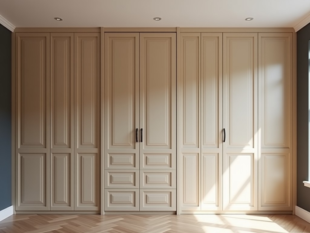
Oem Built In Walk In Closet
OEM built-in walk-in closet systems are engineered storage solutions designed for integration into residential, commercial, and hospitality projects during construction or major renovation. Unlike
- Category:
- Walk In Closet
OEM Built-In Walk-In Closet Systems
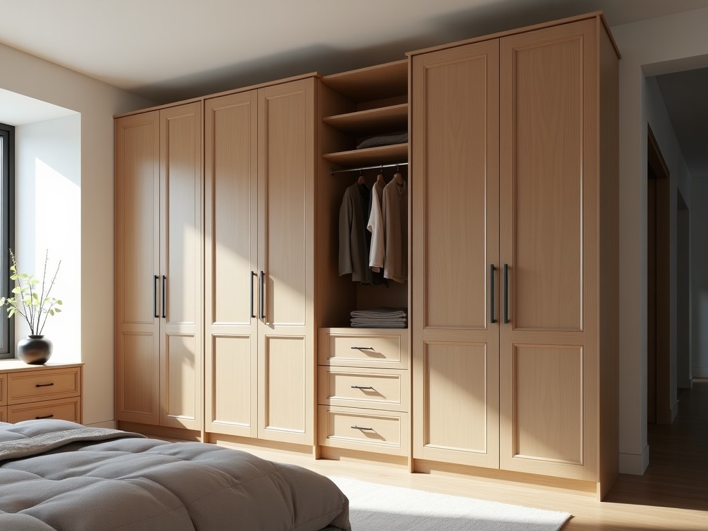
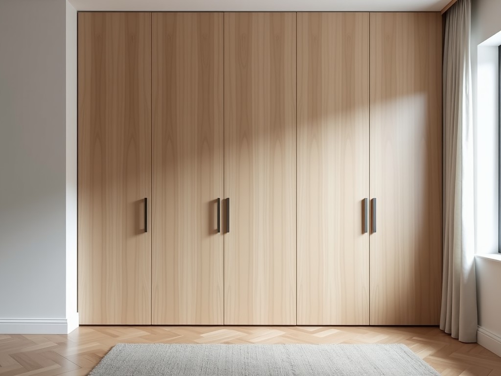
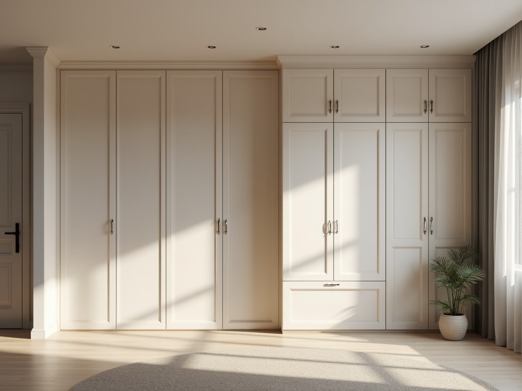
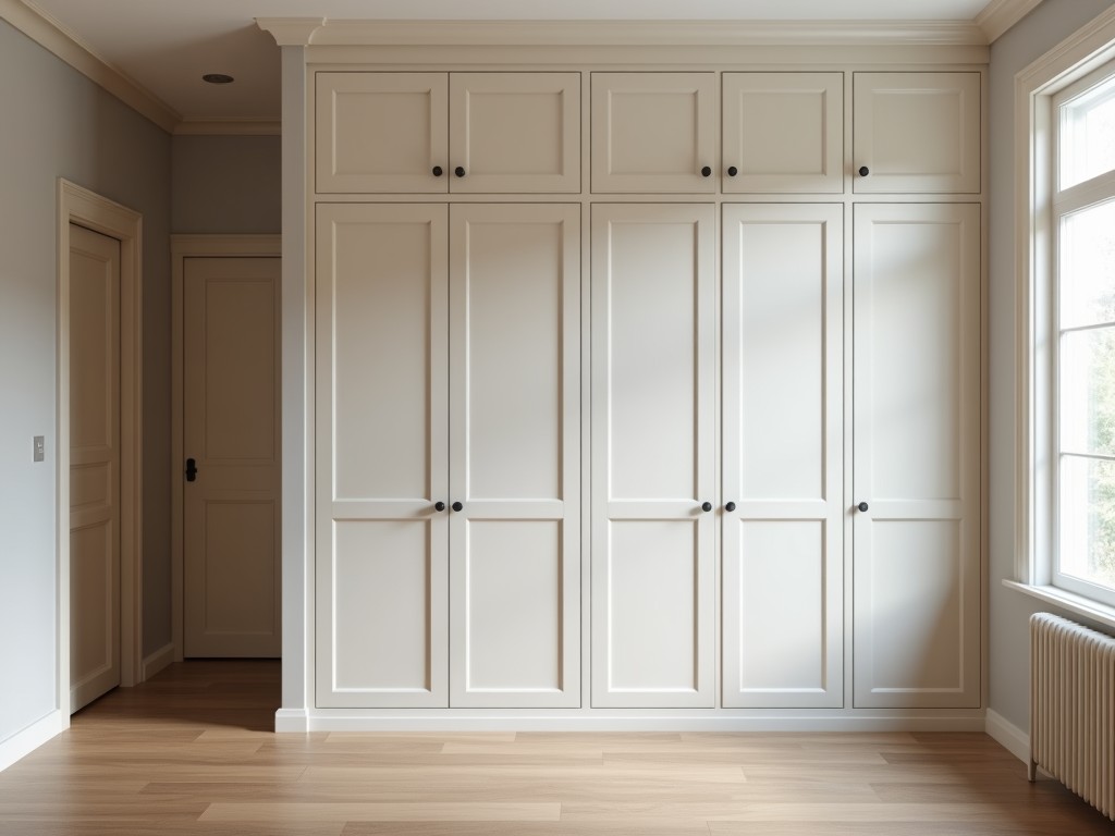
OEM built-in walk-in closet systems are engineered storage solutions designed for integration into residential, commercial, and hospitality projects during construction or major renovation. Unlike freestanding units, these systems are fabricated to exact site dimensions, anchored to structural elements, and configured to maximize usable space within predefined architectural envelopes. They serve as permanent fixtures that combine load-bearing framework, adjustable storage components, and finish materials selected for durability and aesthetic coherence with surrounding finishes.
Structural Framework and Load Distribution
The structural integrity of a built-in walk-in closet depends on its anchoring method and load path design. Vertical supports are typically secured to floor studs, ceiling joists, or adjacent load-bearing walls using mechanical fasteners rated for shear and withdrawal forces. Horizontal runners and shelf standards distribute concentrated loads from hanging rods, shelving, and drawers across multiple anchor points to prevent localized deformation. Engineering calculations consider dynamic loads from daily use, static loads from stored items (e.g., 20–40 kg per linear meter of hanging rod), and seismic or vibration factors in multi-story buildings.
Frame materials are selected based on span requirements, environmental conditions, and finish compatibility. Common options include cold-rolled steel profiles with powder-coated finishes for high-moisture zones, extruded aluminum for lightweight corrosion resistance, and engineered wood composites (e.g., MDF or particleboard with PVC laminate) for dry interior applications where cost and finish uniformity are priorities. Each material undergoes deflection testing under specified load conditions to verify long-term performance without sagging or joint creep.
Storage Component Configuration and Adjustability
Internal storage layouts are defined by modular components that allow reconfiguration without structural modification. Hanging rods are available in fixed or adjustable formats, with load ratings typically ranging from 150 N to 300 N per support bracket depending on diameter and material. Shelving systems use pin-and-hole, rail-mounted, or bracket-supported designs, each offering different adjustability increments (e.g., 25 mm, 32 mm, or 50 mm) and load capacities (commonly 50–150 kg per shelf for 600 mm depth). Drawer modules incorporate full-extension ball-bearing slides rated for 30–50 kg dynamic load, with soft-close mechanisms available as an option.
Accessory integration includes specialized storage for footwear, folded garments, belts, ties, and valuables. Examples include angled shoe shelves (15–20° tilt), pull-out valet rods, vertical dividers for stacks, and lockable inserts. These components are designed to interface with the primary framework using standardized mounting interfaces, ensuring compatibility across product generations and enabling field upgrades without major rework. Custom geometries (e.g., curved ends, angled corners) are fabricated to match architectural constraints while maintaining modular adjustability in adjacent sections.
Finish Materials and Surface Performance
Surface finishes are selected for abrasion resistance, moisture tolerance, and visual consistency with adjacent architectural elements. Common options include melamine-faced panels (MFP) with scratch-resistant overlays, PVC edgebanding for edge protection, and water-based lacquers applied to wood substrates for low-VOC emissions. In high-humidity environments (e.g., bathrooms, coastal regions), marine-grade plywood with phenolic backing or solid-surface composites may be specified to prevent delamination or fungal growth. Finish selection considers cleaning protocols, UV exposure, and thermal cycling expected in the installed location.
Color matching is achieved through standardized RAL or NCS references, with batch-to-batch variation controlled within ΔE < 2.0 for visual uniformity across large installations. Textured finishes (e.g., wood grain, stone effect, matte metallics) are evaluated for light reflectance and fingerprint visibility. Edge treatments — such as 1 mm PVC, 2 mm ABS, or laser-sealed edges — are chosen based on impact resistance requirements and exposure to cleaning equipment. All finishes undergo accelerated aging tests (e.g., 500 hours UV exposure, 48-hour humidity cycling) to validate long-term appearance stability.
Design Integration and Site-Specific Adaptation
OEM built-in systems are developed from detailed site surveys that capture structural constraints, utility penetrations, door swings, and ceiling heights. Laser scanning or photogrammetry is often used to generate accurate as-built models, which inform cabinetry layout to avoid conflicts with HVAC ducts, electrical conduits, or plumbing lines. Design software enables collision detection and clearance verification (e.g., 600 mm minimum front access, 900 mm turning radius for wheelchair access) before fabrication begins. This reduces field modifications and ensures compliance with accessibility standards where applicable.
Adaptation to site conditions includes scribe molding for uneven walls, toe-kick adjustments for uneven floors, and ceiling filler panels for non-planar soffits. Ventilation gaps (typically 5–10 mm) are incorporated at the top and bottom of enclosures to prevent moisture trapping in humid climates. Electrical integration — such as LED lighting with motion sensors, power outlets for charging stations, or data ports for smart mirrors — is planned during the design phase to conceal wiring within chase spaces or behind access panels. These details are coordinated with electrical and HVAC subcontractors during the rough-in phase.
Quality Control and Manufacturing Consistency
Manufacturing follows standardized procedures to ensure dimensional accuracy and finish repeatability across units. CNC cutting achieves panel tolerances of ±0.5 mm, while edge banding is applied using hot-air or laser systems to prevent delamination. Assembly jigs maintain squareness within 1 mm per meter, and hardware installation uses torque-controlled drivers to prevent over-tightening of cam bolts or confirmator screws. Each unit undergoes a pre-assembly check for hole alignment, hardware fit, and surface defect visibility under 500 lux illumination.
Final inspection includes functional testing of all moving parts: drawer slide extension and retraction (10 cycles), hanging rod deflection under load, and shelf pin retention. Finish quality is assessed for color uniformity, edge adhesion, and absence of blisters or orange texture. Packaging uses corner protectors, edge foam, and stretch wrap to prevent damage during transit, with units often shipped flat-pack or partially assembled based on size and fragility. Documentation includes assembly instructions, hardware lists, and maintenance guidelines tailored to the specified finish material.
Typical Applications Across Sectors
In residential construction, built-in walk-in closets are integrated into master bedrooms during the rough-in phase to add perceived value and optimize floor space. Developers specify standardized configurations across units to streamline procurement and installation, while allowing for finish upgrades (e.g., from melamine to lacquer) as a sales option. In multi-family projects, uniformity in dimensions and hardware simplifies maintenance and replacement part logistics over the building lifecycle.
Hospitality applications include guest rooms and suites in hotels, where closets must withstand high turnover and varied user loads. Specifications often emphasize moisture-resistant materials, anti-theft hardware (e.g., locking drawer inserts), and easy-to-clean surfaces. Senior living facilities prioritize accessibility features such as lower hanging rods (1000–1100 mm height), pull-down shelves, and high-contrast interior finishes to aid visibility. Retail environments use built-in systems for stockrooms or employee changing areas, where durability and ease of reconfiguration support seasonal inventory changes.
| Application Sector | Key Design Considerations | Typical Material Choices |
|---|---|---|
| Residential (Single-Family) | Custom layouts, aesthetic integration with bedroom finishes | Melamine-faced panels, PVC edgebanding, wood veneer lacquer |
| Multi-Family Housing | Standardized dimensions, ease of maintenance, cost efficiency | Particleboard with laminate, steel frame, aluminum shelf standards |
| Hospitality (Hotels) | Moisture resistance, security features, high-cycle durability | Marine-grade plywood, solid surface, aluminum frame, ABS edgebanding |
| Senior Living / Assisted Care | Accessibility, ease of use, visibility aids | Laminate with contrasting edges, steel frame, soft-close hardware |
| Commercial / Retail Back-of-House | Durability, reconfigurability, load tolerance | Steel frame, MDF core with PVC laminate, ball-bearing slides |
Customization Logic and Project-Specific Engineering
Customization begins with translating architectural constraints into a modular storage logic. Rather than designing each unit from scratch, engineers apply rule-based systems that adjust module sizes, filler panels, and accessory placement based on input parameters: wall length, height, door opening, and obstructions. For example, a 3000 mm wall with a 600 mm door opening at one end might trigger a combination of 900 mm hanging sections, 600 mm drawer stacks, and 300 mm filler units to maintain symmetry and accessibility. This approach reduces engineering time while ensuring fit-for-purpose outcomes.
Material substitutions are governed by performance thresholds, not aesthetics alone. If humidity exceeds 60% RH consistently, the system triggers a switch from standard MDF to moisture-resistant (MR) grade or plywood, regardless of finish preference. Similarly, if dynamic load on hanging rods exceeds 250 N, the design automatically upgrades bracket thickness or adds intermediate supports. These rules are embedded in configurator software to prevent underspecification and ensure compliance with internal quality benchmarks. Clients receive a bill of materials that references the specific performance criteria driving each selection.
Ordering Process and Technical Preparation
Quotation requires detailed site information to generate an accurate, manufacturable design. Essential inputs include: precise wall-to-wall and floor-to-ceiling measurements (in mm), locations and dimensions of doors/windows, ceiling slope or bulkhead details, and locations of electrical outlets, switches, or HVAC vents. Providing a marked-up floor plan or 3D scan accelerates the review process. Photographs of the installation area help identify unforeseen constraints such as protruding pipes or uneven substrates that may affect anchoring or filler requirements.
Lead times typically range from 4–6 weeks for standard configurations with common finishes, extending to 8–10 weeks for custom geometries, non-standard materials, or integrated electrical components. Shipping is managed via LTL or dedicated truck, with units packaged to resist corner impact and edge chipping. Upon delivery, clients receive assembly drawings, hardware packs, and a checklist for verifying completeness before installation begins. Technical support is available to clarify anchoring methods, adjust for field variations, or confirm compatibility with adjacent trades’ work.