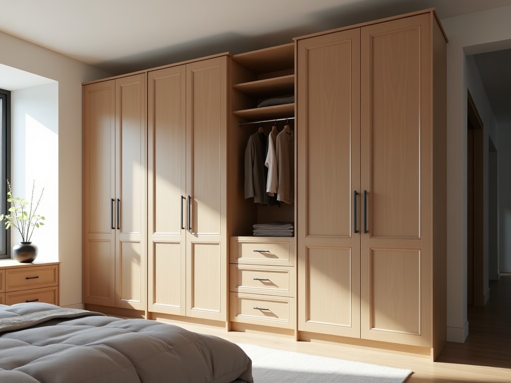
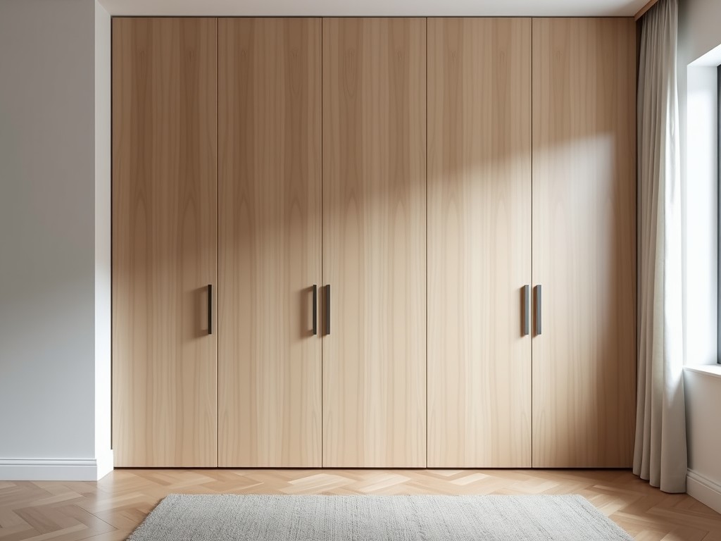
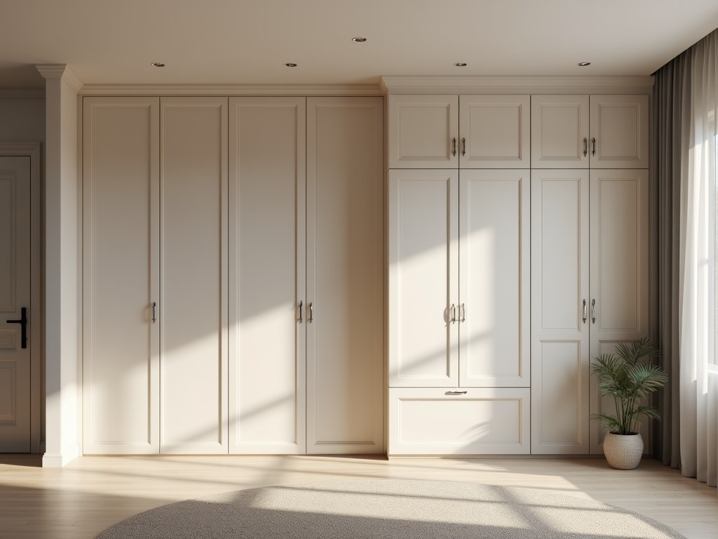
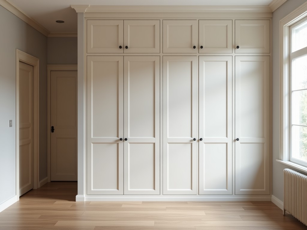
No Floor Contact Wall Wardrobe Unit
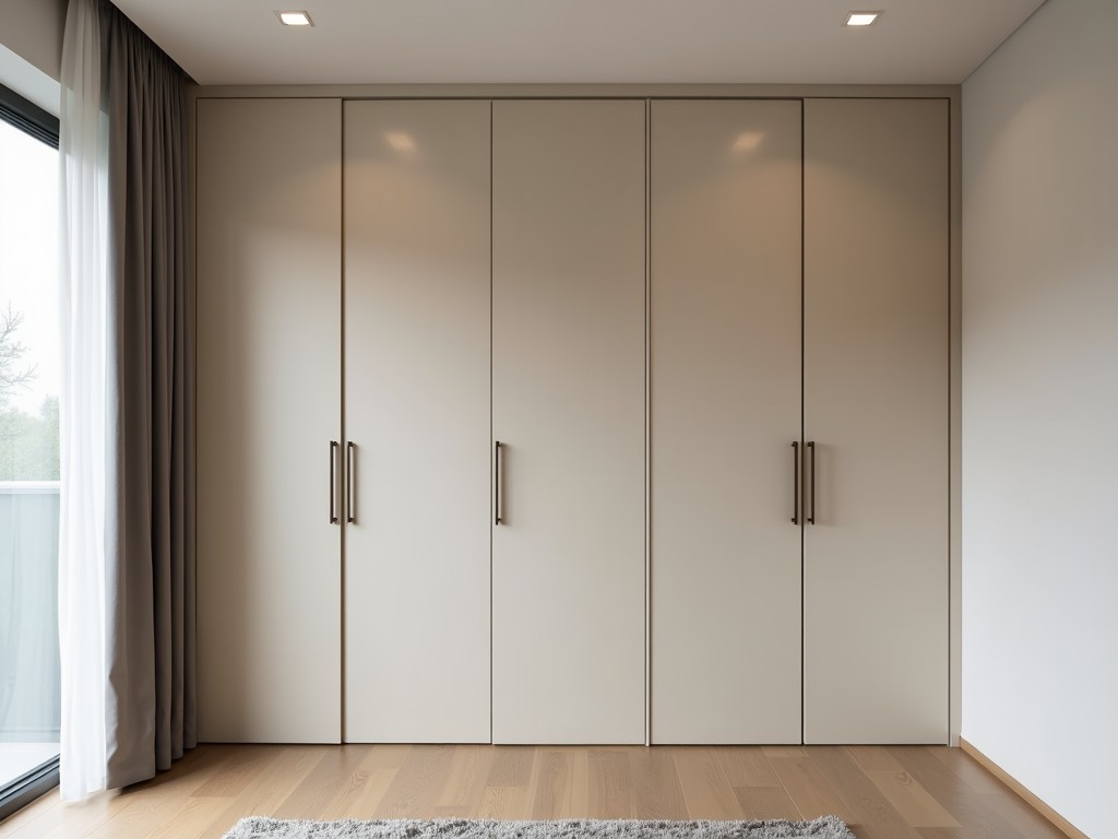
No Floor Contact Wall Wardrobe Unit
A no floor contact wall wardrobe unit is a storage system designed to be mounted directly to structural walls without resting on the floor. This configuration eliminates direct floor loading, reduces
- Category:
- Walk In Closet
No Floor Contact Wall Wardrobe Unit
A no floor contact wall wardrobe unit is a storage system designed to be mounted directly to structural walls without resting on the floor. This configuration eliminates direct floor loading, reduces susceptibility to moisture ingress, and simplifies cleaning in environments where floor hygiene is critical. The unit transfers all dead and live loads to the wall substrate through engineered fastening systems, making it suitable for applications where floor integrity must remain unobstructed or where differential settlement could compromise stability.
Structural Design and Load Transfer
The unit employs a cantilevered framework where vertical load-bearing members are anchored to the wall via high-strength chemical anchors or through-bolts into masonry or steel studs. Horizontal shelves and internal partitions are connected to these vertical members using welded or bolted gussets, creating a rigid space frame. Load analysis shows that over 95% of the total weight—including stored items—is transferred to the wall, with less than 5% residual load distributed through floor-level anti-sway brackets, which serve only to prevent lateral movement, not to support vertical load.
Material Selection and Corrosion Resistance
Primary structural components are fabricated from hot-rolled carbon steel (ASTM A36) or galvanized steel (ASTM A653 SS Grade 33, G90 coating) depending on environmental exposure. In high-humidity or chemically aggressive settings, stainless steel (AISI 304 or 316L) is used for all load-bearing elements. Surface treatment includes phosphate priming followed by epoxy powder coating (minimum 80 µm thickness) or hot-dip galvanizing (minimum 55 µm zinc coating) to achieve salt spray resistance exceeding 500 hours per ASTM B117. Non-structural panels may use powder-coated aluminum or PVC-coated steel for weight reduction where permitted by design.
Modular Configuration and Customization
The system is designed as a modular kit with standardized vertical uprights (available in 2000 mm, 2400 mm, and 3000 mm heights), horizontal rails (400 mm, 600 mm, 800 mm depths), and interchangeable storage modules (shelves, drawers, hanging rods, tote bins). Each module connects via slotted keyhole brackets allowing vertical adjustment in 25 mm increments without tools. Custom lengths are achieved by splicing uprights with internal fishplates and reinforcing with transverse bracing. All interfaces are designed to maintain load path continuity under seismic or dynamic loading conditions.
Installation Requirements and Wall Compatibility
Installation requires a substrate capable of resisting tensile and shear loads from anchor points. Minimum wall specifications include: concrete compressive strength ≥20 MPa, solid clay brick ≥15 MPa, or steel stud backing with ≥0.8 mm thickness and proper blocking. Anchor spacing is determined by tributary load calculations, typically 400–600 mm vertically for uprights. A leveling tolerance of ±3 mm over 2 meters is recommended to ensure proper door alignment and drawer function. Shims are not permitted behind load-bearing anchors; instead, the wall surface must be planar or trimmed to suit.
Typical Applications in Industrial Environments
This unit is commonly specified in pharmaceutical cleanrooms where floor-mounted furniture harbors particulates and impedes wet cleaning protocols. In food processing facilities, it prevents harboring of contaminants beneath units and allows floor drains to remain unobstructed. In electronic manufacturing, it reduces static discharge risks associated with floor-standing metal cabinets on conductive flooring. Automotive plants use it in paint booth corridors where floor space must remain clear for robotic access. Wastewater treatment plants install it in chemical storage rooms to avoid corrosion from splashes and flooding.
Quality Control and Testing
Each unit undergoes dimensional verification of critical interfaces using CMM or calibrated fixtures before coating. Post-coating, adhesion is tested via ASTM D3359 Method B (tape test), requiring minimum 4B rating. Load testing is performed on sample assemblies: vertical uprights are subjected to 1.5× design load for 24 hours with deflection measured at mid-span; permanent set must not exceed 0.25% of span length. Anchor pull-out resistance is validated per ASTM E488 on-site during first installation of each project batch. All welds are inspected visually and via dye penetrant per ASME Section IX standards.
| Parameter | Typical Value | Notes |
|---|---|---|
| Maximum Shelf Load (UDL) | 150 kg/m² | Based on 600 mm shelf depth with central deflection < L/200 |
| Anchor Pull-Out Capacity (Concrete) | ≥15 kN per anchor | M12 chemical anchor, ≥100 mm embedment |
| Vertical Deflection Under Load | < 6 mm at 2000 mm height | With 100 kg point load at top shelf |
| Coating Adhesion (ASTM D3359) | 4B or better | After 500-hour salt spray |
| Adjustment Increment | 25 mm | Vertical shelf positioning |
Ordering and Project Support
To initiate a quotation, provide: wall elevation drawings showing substrate type and obstructions, required internal dimensions (height, width, depth), intended storage load profile (uniform vs. point loads), environmental conditions (temperature, humidity, chemical exposure), and any door or access requirements. Standard lead time is 4–6 weeks after drawing approval. Samples of connection brackets and coating swatches are available upon request. For projects requiring seismic compliance or fire-rated configurations, consult our engineering team during early design phase.