Floating Wall Mounted Closet System
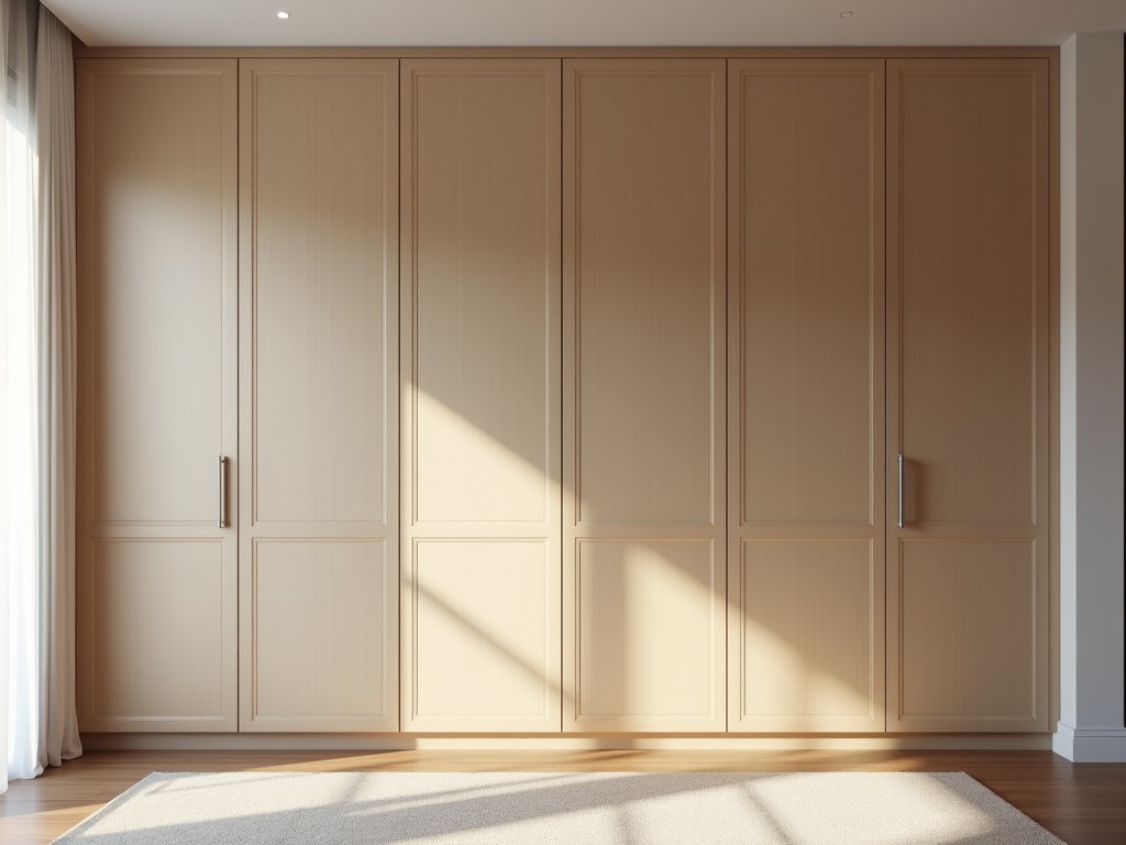
Floating Wall Mounted Closet System
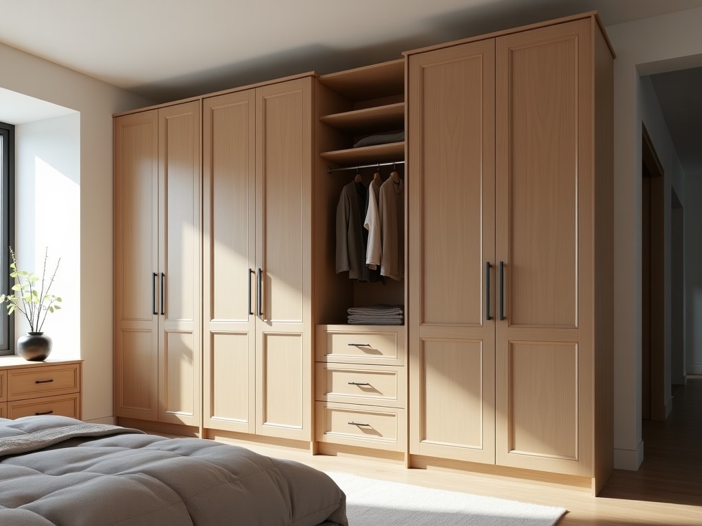
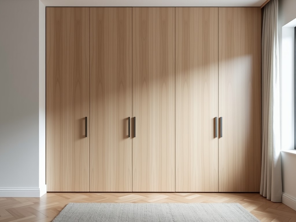
A floating wall mounted closet system is a modular storage solution designed to attach directly to structural walls without visible floor support. The system transfers load through concealed brackets
- Category:
- Walk In Closet
Floating Wall Mounted Closet System
A floating wall mounted closet system is a modular storage solution designed to attach directly to structural walls without visible floor support. The system transfers load through concealed brackets anchored to wall studs or masonry, creating a visually unobstructed floor plane. This configuration is commonly specified in industrial facilities, laboratory environments, and high-traffic commercial spaces where floor accessibility and cleaning efficiency are critical.
Unlike freestanding units, floating systems eliminate floor-based obstructions, reducing trip hazards and simplifying maintenance routines. The absence of legs or base panels also minimizes dust accumulation points, supporting hygiene standards in controlled environments. Load distribution is engineered to concentrate forces at discrete mounting points, requiring precise wall preparation and fastener selection based on substrate type.
Structural Design and Load Capacity
The system utilizes cold-rolled steel brackets with a minimum thickness of 2.5mm, formed into an L-profile to resist both vertical and lateral loads. Each bracket is designed to transfer 180kg of vertical load per mounting point when installed into concrete with M10 chemical anchors, or 120kg into timber studs with 90mm wood screws. Deflection under full load is limited to 1.5mm over a 1000mm span, verified through finite element analysis.
Horizontal reinforcement is provided by a continuous aluminum extrusion rail (6063-T5 alloy) running along the top edge of each panel, preventing racking under asymmetric loading. The rail features a T-slot for attaching adjustable shelving, hanging rods, or drawer modules without compromising structural integrity. Panel-to-rail connection uses stainless steel pins with nylon washers to prevent galvanic corrosion and allow for thermal expansion.
| Mounting Substrate | Anchor Type | Vertical Load per Bracket | Max Panel Span |
|---|---|---|---|
| Concrete (C25/30) | M10 Chemical Anchor | 180kg | 1200mm |
| Timber Stud (C24) | 90mm Wood Screw | 120kg | 1000mm |
| Hollow Block | Sleeve Anchor | 90kg | 800mm |
| Steel Stud (0.9mm) | Self-Drilling Toggle | 100kg | 900mm |
Material Options and Surface Finishes
Panel cores are manufactured from 18mm E1-grade melamine-faced particleboard, providing a density of 650kg/m³ and internal bond strength exceeding 0.8MPa. For environments requiring higher moisture resistance, 18mm marine-grade plywood (BS 1088) or compact laminate (HPL) with a minimum thickness of 12mm are available as alternatives. All edge surfaces are sealed with 2mm PVC edge banding applied via hot-air extrusion to prevent substrate exposure.
Surface finishes include low-pressure melamine (LPM) in standard colors (white, light gray, beige), high-pressure laminate (HPL) for abrasion resistance (Taber wear index <80mg/1000 cycles), and powder-coated steel panels (60µm thickness, gloss level 20-30%) for chemical exposure zones. Anodized aluminum trims (15µm thickness) are used on exposed edges to enhance impact resistance and provide a consistent visual profile across material transitions.
- Melamine-faced particleboard: Standard for dry offices, retail displays
- Marine plywood: Selected for laboratories, washdown areas
- Compact laminate: Used in food processing, chemical storage
- Powder-coated steel: Specified for welding zones, battery rooms
Customization and Module Integration
The system supports dimensional customization in 50mm increments for width, height, and depth, with standard panel depths of 300mm, 450mm, and 600mm to accommodate varying storage requirements. Depth extension beyond 600mm requires intermediate vertical supports to maintain deflection limits. Internal accessories include adjustable shelving (25mm increment increments), pull-out drawers with 40kg load capacity, and hanging rods rated for 25kg linear load.
Electrical integration is facilitated through pre-punched rear panels for conduit routing and optional cable management channels (40x25mm PVC) mounted internally. Lighting provisions include low-voltage LED strips (12V, 4.8W/m) with motion sensors, powered via centralized drivers mounted in adjacent utility closets. All modifications are engineered to maintain structural continuity and do not compromise load path integrity.
Finish matching is available for corporate color standards using RAL or Pantone references, with powder coating or HPL lamination applied to meet specified tolerances (±2ΔE). Custom branding via laser etching or screen printing is offered on panel surfaces for OEM applications, with adhesion tested per ASTM D3359 Method B.
Installation Requirements and Site Preparation
Installation requires verification of wall flatness within 3mm over a 2000mm straightedge and substrate suitability per the load table above. Masonry walls must be cleaned of loose debris and primed with epoxy bonding agent where chemical anchors are used. Timber studs require confirmation of grade and spacing (typically 400mm or 600mm on-center) before fastener selection.
A minimum 50mm clearance is required behind the system for ventilation and service access, increasing to 100mm if electrical conduits are routed vertically. Floor clearance beneath the lowest panel is typically set at 150mm to allow for cleaning equipment passage, though this can be adjusted based on specific equipment dimensions. All mounting points must be marked using a laser level to ensure vertical alignment within 1.5mm over 2000mm.
- Wall flatness: ≤3mm deviation over 2m
- Minimum embedment depth: 90mm for chemical anchors
- Torque specification: 25Nm for M10 anchors
- Panel gap tolerance: ±1.5mm between adjacent units
Quality Control and Testing
Each production batch undergoes dimensional inspection using calibrated CMM equipment, with critical dimensions (hole positions, panel squareness) held to ±0.5mm tolerance. Load testing is conducted on 10% of batches using hydraulic rams to verify ultimate failure points, with a minimum safety factor of 4:1 applied to published ratings. Surface finish adhesion is tested via cross-hatch method (ASTM D3359) requiring minimum 4B rating for all coated surfaces.
Panel-to-bracket connection strength is validated through cyclic load testing (10,000 cycles at 50% rated load) to ensure long-term reliability under repeated use. Edge sealing integrity is checked using dye penetrant inspection to confirm full encapsulation of substrate edges. All test results are retained for traceability and provided upon request as part of the technical documentation package.
Material certifications include FSC or PEFC chain-of-custody for wood-based panels, and REACH compliance for all surface finishes and adhesives. Fire performance testing is available upon request, with standard LPM panels achieving Class D-s2,d0 per EN 13501-1, and HPL options reaching Class B-s2,d0. Electrical components comply with IEC 60335-2-29 for household storage units, adapted for industrial use.
Inquiry and Technical Support
For project-specific configurations, load calculations, or material substitutions, contact our technical team with the following details: wall substrate type and condition, required panel dimensions, intended load distribution (uniform or point load), environmental conditions (humidity, temperature, chemical exposure), and any required integrations (electrical, lighting, accessories).
Provide site drawings or sketches showing wall elevations and obstructions to facilitate accurate bracket placement and panel layout. Our engineers will return a detailed proposal including load analysis, fastener schedule, and installation instructions within two business days. Standard lead time for configured units is 3-4 weeks, with expedited options available for critical projects.
Samples of panel materials, edge finishes, and bracket types are available upon request, shipped via courier with protective packaging. All inquiries are treated confidentially and used solely for project estimation purposes.
Request Technical Consultation