Tv Wall Mount With Cabinet
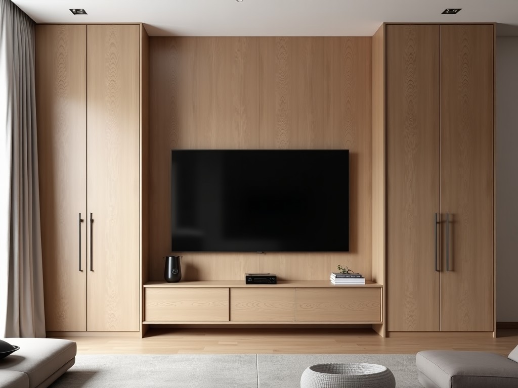
Tv Wall Mount With Cabinet
A TV wall mount with cabinet combines a load-bearing mounting system with enclosed storage, designed to secure flat-panel displays while concealing cables, media components, and accessories. This
- Category:
- TV Cabinet
TV Wall Mount with Integrated Cabinet
A TV wall mount with cabinet combines a load-bearing mounting system with enclosed storage, designed to secure flat-panel displays while concealing cables, media components, and accessories. This integrated solution addresses both mechanical stability and spatial organization in environments where floor space is limited or aesthetic integration is required.
Unlike standard mounts that only support the display, this system incorporates a rigid rear plate, adjustable arms, and a ventilated cabinet enclosure that maintains access to AV equipment while protecting it from dust, unauthorized access, and accidental impact. The cabinet is structurally tied to the mount to ensure load paths remain aligned under dynamic and static conditions.
Load Capacity and Structural Design
The mount’s load-bearing capacity is determined by the wall interface, arm length, and material thickness of the mounting plate. Typical configurations support displays weighing between 20 kg and 45 kg, with safety factors of 4:1 applied to static loads. The cabinet adds 3–8 kg of dead load, which must be included in total weight calculations.
The mounting plate uses cold-rolled steel with a minimum thickness of 2.5 mm, formed into a box section to resist bending under cantilever loads. Wall attachment points are spaced to align with standard stud spacing (400 mm or 600 mm) and use M8 or M10 lag bolts with washers to distribute shear and tensile forces. Arm extensions are fabricated from extruded aluminum with internal reinforcement ribs to limit deflection under load.
Cabinet panels are constructed from 1.2 mm galvanized steel or powder-coated aluminum, with internal dividers optional for component separation. Ventilation is achieved through passive convection via top and bottom perforations, calculated to maintain internal temperatures within 10°C of ambient when housing devices with combined power draw under 60 W.
Adjustability and Viewing Geometry
The mount offers three-axis adjustment: horizontal swing (±45°), vertical tilt (+5°/-15°), and rotational leveling (±3°) to compensate for wall imperfections. Arm extension ranges from 50 mm to 400 mm, allowing the display to be positioned flush against the wall or extended for viewing angle adjustment. Each axis uses detented, tool-free locking mechanisms with torque ratings sufficient to resist vibration-induced drift.
The cabinet is fixed relative to the wall plate, so display movement does not affect enclosure alignment. Internal shelving is adjustable in 25 mm increments to accommodate varying component heights (e.g., soundbars, streaming boxes, routers). Cable ports are located at the rear and base of the cabinet, fitted with grommets to prevent abrasion and maintain ingress protection.
Material Selection and Environmental Resistance
Primary structural components use SPCC cold-rolled steel for the mounting plate and arms, treated with zinc phosphate pretreatment and electrostatic powder coating (80–120 µm thickness) for corrosion resistance in indoor environments. Cabinet panels may be specified in SECC galvanized steel or 5052-H32 aluminum for applications requiring higher humidity tolerance or chemical exposure resistance.
All fasteners are stainless steel (A2-70) to prevent galvanic corrosion at dissimilar material interfaces. Powder coating options include RAL 9005 (black), RAL 9016 (white), or custom colors upon request. Surface hardness exceeds 2H pencil rating, and adhesion passes 5B cross-hatch testing per ASTM D3359.
For installations in environments with elevated particulate levels (e.g., workshops, control rooms), optional sealed cabinet variants are available with IP54-rated door seals and filtered ventilation paths. These variants reduce internal dust accumulation by approximately 70% compared to unsealed designs under identical conditions.
Typical Applications in Industrial and Commercial Settings
This product is commonly specified in medical imaging rooms where displays must be positioned at eye level while storing image processors, printers, and control units below. The enclosed cabinet prevents contamination of sensitive equipment and allows for quick access during maintenance without exposing components to ambient air.
In industrial control centers, the mount secures HMI displays above PLCs, HMIs, and network switches, keeping floor space clear for operator movement. The cabinet’s lockable door (optional) prevents unauthorized tampering with critical networking gear while allowing ventilation to prevent thermal throttling of processors.
Retail and hospitality installations use the system to mount menu boards or informational displays above point-of-sale terminals, with the cabinet storing media players, routers, and backup power units. The integrated design reduces visual clutter and minimizes the number of wall penetrations required for power and data cables.
| Parameter | Typical Value | Notes |
|---|---|---|
| Max Display Weight | 45 kg | Includes safety factor of 4:1 |
| Mounting Plate Thickness | 2.5 mm | Cold-rolled steel, box-section |
| Arm Extension Range | 50–400 mm | Adjustable in 50 mm increments |
| Cabinet Internal Height | 120–200 mm | Adjustable shelving |
| Ventilation Area | 80 cm² (top + bottom) | Passive convection, <60 W load |
| Surface Finish | Powder coating, 80–120 µm | RAL 9005 standard, customizable |
Installation and Integration Considerations
Installation requires verification of wall substrate strength and stud location. For metal stud walls or concrete substrates, alternative fastening methods (e.g., toggle bolts, chemical anchors) must be evaluated based on pull-out and shear ratings. The mounting plate includes horizontal sliders to allow ±25 mm positional adjustment post-installation to align with studs.
Electrical routing should be planned to avoid sharp bends near cable ports. Power and data cables should be segregated within the cabinet to minimize EMI interference. For installations requiring future service access, leave a minimum of 50 mm clearance above the cabinet for door swing and tool access.
The product is shipped in two packages: one for the mount assembly and arms, another for the cabinet panel and hardware. Assembly requires basic hand tools (socket wrenches, Phillips drivers) and takes approximately 20–30 minutes per unit. All fasteners are pre-threaded or self-tapping where applicable to reduce installation time.
Quality Control and Manufacturing Consistency
Each mount undergoes dimensional verification of critical interfaces using CMM or calibrated fixtures, with tolerances held to ±0.5 mm on hole patterns and arm pivot points. Load testing is performed on a sampling basis per batch, applying 1.5× rated load for 10 minutes to detect plastic deformation or joint slip.
Powder coating thickness and adhesion are checked using magnetic gauges and cross-hatch tape tests on every fifth unit. Cabinet door alignment is verified by measuring gap uniformity across all four sides, with acceptable variation not exceeding 1.0 mm. All units receive a final visual inspection for surface defects, scratches, or incomplete fastening.
Material traceability is maintained for structural steel and fasteners, with mill certificates available upon request. Packaging includes corrosion inhibitors and edge protectors to prevent damage during transit. Units are stacked no higher than 5 per pallet to avoid deformation of lower items under load.
For OEM inquiries, customization of cabinet dimensions, hole patterns for specific display models, or integration of locking mechanisms is possible. Lead times for standard configurations are typically 3–4 weeks; modified designs require additional review time. Contact technical support for project-specific evaluations.
To discuss your specific mounting and storage requirements, request a technical quotation, or obtain CAD models and installation guides, contact our engineering team.
Request Technical Consultation