Tv Wall Hung Cabinet Unit Factory
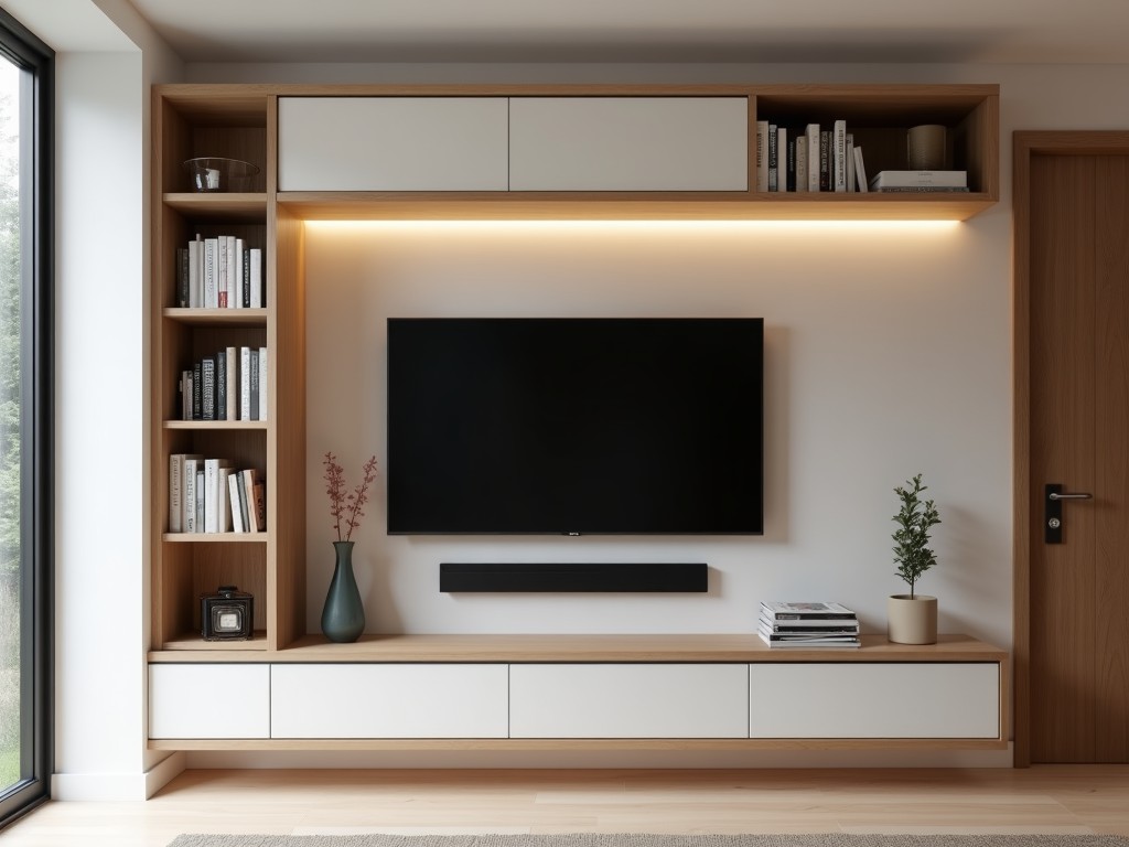
Tv Wall Hung Cabinet Unit Factory
Industrial procurement for wall-mounted TV cabinets requires precise technical alignment between manufacturing capabilities and project requirements. This document outlines the engineering
- Category:
- TV Cabinet
TV Wall Hung Cabinet Unit Factory: Engineering Specifications and Manufacturing Capabilities
Industrial procurement for wall-mounted TV cabinets requires precise technical alignment between manufacturing capabilities and project requirements. This document outlines the engineering parameters, material considerations, and production workflows relevant to sourcing TV wall hung cabinet units from a dedicated manufacturing facility.
Understanding these specifications enables buyers to evaluate supplier suitability, reduce design iteration cycles, and ensure long-term performance in commercial and residential installations.
Core Structural Design Parameters
TV wall hung cabinet units are engineered as load-bearing assemblies designed to safely support static and dynamic loads from display equipment while maintaining dimensional stability under varying environmental conditions.
Primary structural considerations include:
- Dead load capacity: Typically rated for 50–150 kg depending on substrate anchoring and frame geometry, verified through finite element analysis (FEA) during design validation.
- Dynamic load resistance: Designed to withstand vibrational forces from speaker output and occasional impact, with natural frequency avoidance above 20 Hz to prevent resonance.
- Deflection limits: Maximum allowable sag under full load is constrained to L/200 (where L is span) to prevent visible deformation or stress on mounting interfaces.
Frame geometry is optimized using box-section reinforcements or lattice stiffening to maximize torsional rigidity while minimizing material mass, critical for reducing anchor pull-out risk in gypsum or hollow masonry substrates.
Material Selection and Substrate Compatibility
Material choice directly influences corrosion resistance, fire performance, weight, and finish durability. Selection is guided by project-specific environmental exposure and regulatory requirements.
| Material Type | Typical Thickness | Surface Finish Options | Key Considerations |
|---|---|---|---|
| Cold-rolled steel (SPCC) | 0.8–2.0 mm | Powder coating (RAL colors), galvanzied primer | High strength-to-weight ratio; requires primer for humid environments |
| Stainless steel (SS304/SS316) | 1.0–1.5 mm | Brushed, polished, or powder coated | Preferred for coastal, high-humidity, or sanitary environments; higher material cost |
| Aluminum alloy (6063-T5) | 1.2–2.5 mm | Anodized (clear or color), powder coated | Lightweight (⅓ steel); lower modulus requires larger sections for equivalent stiffness |
| Engineered wood (MDF/particleboard) | 16–25 mm | Veneer, laminate, lacquer, PVC edge band | Used for non-structural facades; requires steel subframe for load-bearing applications |
Substrate compatibility is addressed through modular anchoring systems. Factory-supplied hardware includes:
- Chemical anchor bolts for concrete or solid brick (M8–M10, embedment depth ≥ 80 mm)
- Toggle bolts or spread anchors for hollow wall applications (plasterboard, metal stud)
- Adjustable mounting brackets with ±10 mm vertical and horizontal tolerance for field alignment
All anchoring components are supplied with corrosion-resistant coatings (zinc-nickel or passivated stainless) and pre-drilled hole templates to ensure repeatable installation accuracy.
Manufacturing Process and Tolerance Control
Production follows a sequential workflow designed to maintain dimensional accuracy and surface integrity from raw material to finished unit. Key process stages include:
- CNC laser or punch cutting: Panel blanks cut to ±0.1 mm positional accuracy; kerf compensation applied for material thickness variation.
- Press brake bending: Angles controlled to ±0.5° using CNC backgauges and angle encoders; springback compensated via empirical tooling data.
- Robotic welding (MIG/TIG): Intermittent stitch welding on load paths; heat input monitored to limit distortion (<0.5 mm warp over 300 mm span).
- Surface preparation: Degreasing, phosphating, and rinsing prior to coating; surface profile Ra 1.6–3.2 μm for optimal adhesion.
- Powder coating: Electrostatic application (60–80 μm thickness); cured at 180–200°C for 10–15 mins; film hardness ≥2H (pencil test), adhesion ≥5B (tape test).
- Final assembly: Insertion of dampers, cable grommets, and ventilation inserts; torque-controlled fastening (M4–M6, 1.5–3.0 Nm) to prevent substrate cracking.
In-line quality checks are performed at each stage using coordinate measuring machines (CMM) for critical dimensions and spectrophotometers for color consistency (ΔE < 1.5 vs. standard).
Customization Logic and Engineering Support
Customization is driven by functional requirements rather than aesthetic preferences alone. The factory accommodates engineering-led modifications through:
- Parametric design models: Adjustable variables include width (400–1800 mm), height (200–600 mm), depth (150–350 mm), and load rating (25–200 kg).
- Mounting interface adaptation: VESA pattern compliance (75×75 to 800×400 mm), custom bracket patterns, or integrated soundbar shelves.
- Thermal management: Perforation patterns or passive vents designed based on CFD analysis of equipment heat dissipation (typically 50–200 W).
- Cable management: Molded channels, brush strips, or removable panels with IP20-rated ingress protection for dust.
Engineering support includes:
- Load verification: Submission of substrate specifications (concrete grade, stud spacing, wall construction) enables factory to provide anchor load calculations and safety factors.
- Finish matching: Provision of RAL or Pantone references allows batch-specific powder coating to align with adjacent architectural elements.
- Prototyping: First-article inspection (FAI) reports include CMM data, coating thickness maps, and load test results prior to production release.
All customizations are subject to design for manufacturability (DFM) review to ensure tooling feasibility, minimize secondary operations, and maintain cost predictability.