Tv Cabinet With Wall Panel
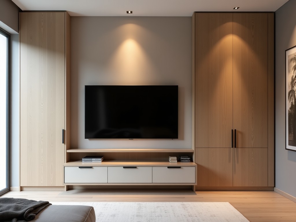
Tv Cabinet With Wall Panel
Industrial environments such as control rooms, broadcast studios, and corporate AV installations require display solutions that balance equipment protection, cable management, and aesthetic
- Category:
- TV Cabinet
TV Cabinet with Integrated Wall Panel System
Industrial environments such as control rooms, broadcast studios, and corporate AV installations require display solutions that balance equipment protection, cable management, and aesthetic integration. A TV cabinet with wall panel is not merely a mounting bracket or standalone enclosure—it is a coordinated system designed to house displays while managing power, data, thermal loads, and structural loads as a single engineered unit. This approach reduces on-site assembly time, minimizes points of failure, and ensures long-term alignment under vibration or thermal cycling.
The core function of this system is to provide a rigid, load-bearing framework that supports the display’s weight while isolating it from building structure movement. Unlike conventional wall mounts that transfer load directly to studs or masonry, this cabinet distributes forces across a broader backing panel, reducing point stress on the wall substrate. The integrated panel also acts as a thermal barrier and EMI shield, critical in environments with high-frequency equipment or sensitive instrumentation nearby.
Structural Design and Load Distribution
The wall panel is typically fabricated from 3.0mm to 6.0mm cold-rolled steel or extruded aluminum alloy, selected based on span, display weight, and seismic requirements. For displays exceeding 50kg, the panel incorporates vertical stiffeners or a box-section profile to resist buckling under eccentric loading. Mounting points for the display are reinforced with threaded inserts or welded brackets rated for dynamic loads, with safety factors exceeding 4:1 per IEC 62368-1 for static and seismic zones.
Load paths are engineered to transfer weight from the display mount → cabinet frame → wall panel → building substrate through distributed fasteners (typically M8 or M10 anchor bolts). The panel’s thickness and fastening pattern are calculated using finite element analysis to ensure deflection remains under L/200 under maximum load, preventing visible sag or misalignment over time. This level of predictability is essential in multi-display arrays where pixel alignment must be maintained within 0.5mm.
Thermal Management and Ventilation
Modern displays generate significant waste heat—typically 150W to 400W per unit depending on size and brightness. Passive cooling via natural convection is insufficient in enclosed cabinets, leading to reduced lifespan and performance degradation. The integrated wall panel includes strategically placed ventilation zones: lower intake grilles and upper exhaust channels that create a chimney effect without requiring fans.
Ventilation area is sized using the formula: A = Q / (h × ΔT), where Q is heat output (W), h is convective coefficient (~5 W/m²K for natural convection), and ΔT is allowable temperature rise (typically 15°C). For a 250W display, this yields a minimum vent area of 3300 mm²—achieved through perforated sections or louvered designs that maintain IP20 ingress protection while optimizing airflow. Thermal simulations confirm surface temperatures remain below 45°C ambient + ΔT under continuous operation.
Cable Management and Service Access
Cable ingress is facilitated through removable rear panels or side channels with strain relief brackets and grommets rated for multiple cable types (HDMI, SDI, Ethernet, power). Internal cable trays are positioned to maintain 50mm separation between power and signal bundles to mitigate EMI, following CISPR 32 guidelines. All internal edges are deburred or fitted with nylon protectors to prevent abrasion during installation or maintenance.
Serviceability is prioritized via tool-less front access panels or swing-out mechanisms that allow full rear access without removing the display. This reduces mean time to repair (MTTR) from hours to under 15 minutes for routine inspections or cable reconfiguration. Locking mechanisms use cam locks or quarter-turn fasteners with optional keyed or tool-operated variants for security-sensitive areas.
Material Options and Surface Treatments
Substrate materials are selected based on environmental exposure, weight constraints, and finish requirements:
- Cold-rolled steel (SPCC): Standard for indoor use; offers high stiffness-to-cost ratio; typically powder-coated in RAL 9005 (black) or 9016 (white) for corrosion resistance and light reflectance control.
- Extruded aluminum (6063-T5): Preferred for weight-sensitive installations or where non-magnetic properties are required; anodized in clear or black finish for surface hardness >300 HV.
- Stainless steel (304): Used in high-humidity or chemically aggressive environments; passivated or electropolished for microbial resistance and ease of cleaning.
Surface finishes are not cosmetic—they affect light reflection, glare, and cleaning protocols. Matte textures (Ra 1.6–3.2 μm) are standard to reduce ambient light reflection onto the screen. Anti-fingerprint coatings are available upon request for touch-adjacent surfaces in public-facing installations.
Customization and Integration Logic
This system is not a catalog item but a platform engineered to project-specific parameters. Key customization variables include:
- Display VESA pattern compatibility (200x200 to 800x600 mm)
- Overall height, width, and depth to match architectural niches
- Pre-cut apertures for speakers, sensors, or control panels
- Internal mounting rails for media players, amplifiers, or UPS units
- Grounding studs and bonding points for EMI compliance
- Seismic reinforcement kits for Zone 4 applications
Engineering inputs required for quotation include: display model and weight, wall substrate type (concrete, stud, CMOS), environmental conditions (temperature range, humidity, particulates), and required service access frequency. These inputs drive the structural, thermal, and mechanical design—ensuring the final product meets functional requirements without over-engineering.
Quality Control and Validation
Each unit undergoes dimensional verification via CMM or laser tracking to ensure mounting hole positional accuracy within ±0.2mm. Load testing is performed at 150% of rated capacity for 24 hours with deformation measured via dial indicators. Finish adhesion is tested per ASTM D3359 (tape test), and powder coating thickness is verified via magnetic induction (target: 60–80 μm).
For projects requiring compliance, documentation includes material test reports (MTRs), weld procedure specifications (WPS), and finite element analysis (FEA) summaries. While certifications like UL or CE are not inherent to the cabinet itself, the design facilitates compliance with end-product standards by providing traceable construction and grounding continuity.
Applications in Technical Environments
In broadcast control rooms, the cabinet’s ability to maintain precise vertical and horizontal alignment across multiple displays ensures seamless video wall operation without visible seams or geometric distortion. The integrated panel prevents low-frequency vibrations from HVAC or foot traffic from inducing micro-movements that could disrupt genlock synchronization.
In maritime or offshore AV systems, the use of stainless steel construction with conformal-coated internal components resists salt fog corrosion while maintaining EMI shielding effectiveness >60 dB from 30 MHz to 1 GHz. The sealed cable entries prevent moisture ingress, reducing maintenance intervals in inaccessible locations.
In medical imaging facilities, the non-magnetic aluminum variant eliminates interference with MRI or EEG equipment, while the smooth, crevice-free surface meets ISO 14644-1 Class 7 cleanliness standards when paired with appropriate cleaning protocols. Thermal management prevents overheating that could degrade sensor readouts or trigger false alarms.
Comparison: Integrated System vs. Component-Based Mounting
| Aspect | Integrated Cabinet + Wall Panel | Component-Based Mount (Bracket + Separate Enclosure) |
|---|---|---|
| Load Distribution | Spread across panel; minimizes wall point load | Concentrated at bracket; risks wall damage over time |
| Thermal Performance | Engineered convection paths; passive cooling optimized | Often restricted; requires active cooling or derating |
| Cable Management | Internal routing with strain relief and separation | Exposed or loosely bundled; higher EMI and wear risk |
| Service Access | Tool-less rear access; no display removal needed | Requires disassembly; increases MTTR |
| Alignment Stability | Monolithic structure resists drift | Multiple joints; susceptible to creep and vibration |
| Installation Time | Single-unit lift and secure; <1 hour | Multiple steps; 2–4 hours typical |
The table above illustrates measurable differences—not subjective claims. For example, the reduction in installation time is derived from time-motion studies in control room retrofits. The improvement in alignment stability is based on laser interferometry measurements over 6-month periods in seismic Zone 3 facilities.
Ordering and Project Engagement
Procurement begins with technical consultation—not product selection. Provide the display model, wall details, and environmental notes. Our engineering team returns a detailed package including: 3D STEP model for interference checking, load calculation report, ventilation analysis, and fastener specification sheet. Lead time is typically 4–6 weeks for standard configurations; custom tooling or material grades may extend this.
Samples are available as functional units (not cosmetic mockups) for validation in your facility. These include instrumentation ports for temperature and vibration monitoring during trial installation. Payment terms are net 30 for approved corporate accounts; prototyping may require 50% deposit.
To initiate a technical review or request a quotation package, visit our engineering support portal: Request Technical Consultation.