Tv Background Display Wall Cabinet
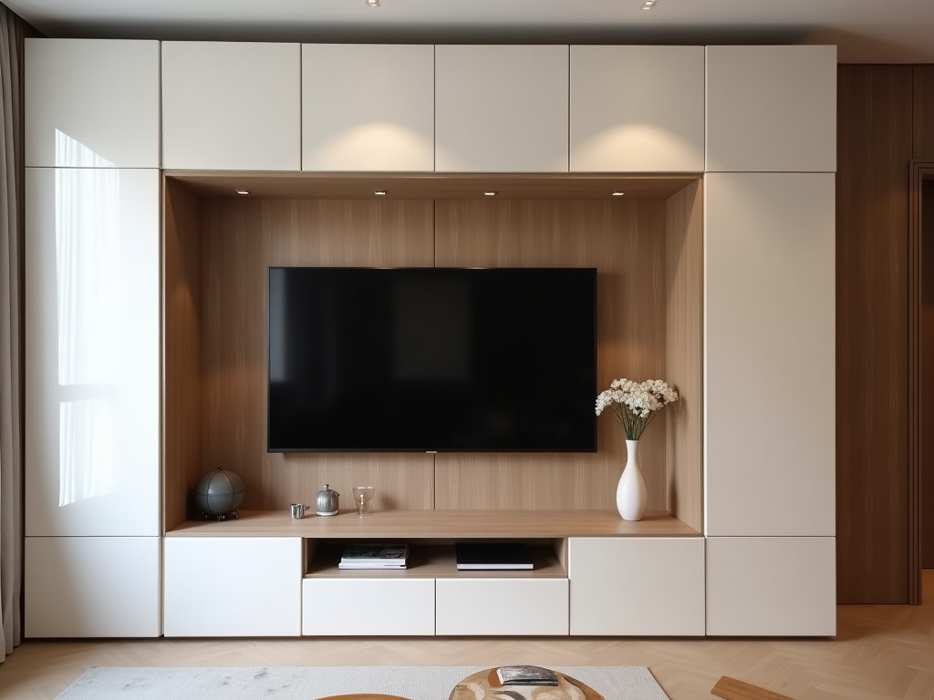
Tv Background Display Wall Cabinet
A TV background display wall cabinet integrates structural support, cable management, and aesthetic finishing into a single engineered unit designed for mounting flat-panel displays in commercial,
- Category:
- TV Cabinet
TV Background Display Wall Cabinet
A TV background display wall cabinet integrates structural support, cable management, and aesthetic finishing into a single engineered unit designed for mounting flat-panel displays in commercial, institutional, and residential environments. Unlike standalone TV mounts or decorative shelving, this system combines load-bearing capacity with concealed wiring pathways and surface treatments that align with interior architectural details. The primary function is to securely position the display at optimal viewing height while eliminating visual clutter from power cords, HDMI cables, and mounting hardware.
Material selection directly impacts long-term performance and installation flexibility. Common substrates include cold-rolled steel for structural frames due to its yield strength (typically 250–350 MPa) and resistance to deformation under sustained load, medium-density fiberboard (MDF) with laminated finish for surface panels offering dimensional stability and compatibility with veneers or paint, and aluminum extrusions for edge trim providing corrosion resistance and clean lines. Surface finishes may involve powder coating (60–80 µm thickness) for metal components or melamine-faced panels for wood-based sections, selected based on environmental exposure and maintenance requirements.
Load capacity is determined through finite element analysis and physical testing, accounting for both static weight of the display and dynamic forces during installation or adjustment. Typical configurations support displays ranging from 32 to 86 inches with weights up to 60–80 kg, depending on frame geometry and wall anchoring method. Critical design factors include center-of-gravity alignment, screw pull-out strength in the substrate (concrete, stud, or hollow wall), and deflection limits under load—usually restricted to L/200 or less to prevent visible sagging over time. These parameters are validated per project using manufacturer-provided load charts.
Cable management is not an add-on but a core design consideration. Internal channels, typically 20–30 mm wide and 15–20 mm deep, run vertically and horizontally within the cabinet structure to route power, data, and AV cables from the display to floor or wall outlets. These channels feature removable access panels or snap-in covers, allowing maintenance without disassembly. Bend radii inside channels are maintained above 10 mm to prevent cable damage, and separation between low-voltage (HDMI, Ethernet) and high-voltage (AC power) paths follows EMI best practices, often using internal dividers or staggered routing.
Installation method depends on wall type and load requirements. For concrete or masonry walls, chemical anchors or mechanical expansion bolts are used with embedded steel plates welded to the cabinet frame. On wood stud walls, lag screws penetrate multiple studs with washers to distribute load. In hollow-wall applications (e.g., drywall over metal studs), toggle bolts or snap-toggles are specified, often combined with a load-spreading backing plate mounted behind the wall surface. Each method requires verification of substrate integrity and torque specifications during installation to prevent creep or pull-out failure.
Customization options address project-specific constraints without compromising structural integrity. Dimensions—height, width, depth—are adjusted to match display size, viewing height (typically 100–120 cm from floor to center of screen), and room architecture. Depth varies from 80–120 mm for slim profiles to 150–200 mm when accommodating soundbars, media players, or ventilation space. Surface finishes can be matched to existing millwork via RAL or NCS color codes, wood grain laminates, or textured coatings. Integrated lighting (LED strips with diffusers) or acoustic backing panels may be added based on environmental needs.
| Parameter | Typical Range / Option | Notes |
|---|---|---|
| Max Display Weight | 60–80 kg | Dependent on frame design and wall anchors |
| Frame Material | Cold-rolled steel (1.2–2.0 mm) | Yield strength 250–350 MPa |
| Panel Material | MDF (16–18 mm) or Plywood | Laminated or veneered finish |
| Cable Channel Size | 20–30 mm W × 15–20 mm D | Removable covers, EMI separation |
| Surface Finish | Powder coating, melamine, veneer | Customizable to RAL/NCS |
| Installation Depth | 80–200 mm | Depends on accessories and ventilation |
Environmental considerations influence material and finish selection. In high-humidity areas (e.g., lobbies near coastal regions or spas), powder-coated steel with UV-stable pigments prevents corrosion and fading. For environments requiring frequent cleaning (healthcare, education), non-porous surfaces such as thermofoil-laminated MDF or stainless steel trim resist moisture and chemical exposure. Thermal management is addressed through passive ventilation gaps at top and bottom edges or optional fan mounts, ensuring operating temperatures remain within display manufacturer specifications—typically below 40°C ambient to avoid performance degradation.
Applications extend beyond simple mounting. In corporate settings, these cabinets support video conferencing displays in meeting rooms where clean aesthetics and cable concealment reduce distractions. In retail environments, they house digital signage behind branded surrounds that match store fixtures, enabling seamless integration into architectural millwork. Control rooms use reinforced variants with dual-monitor configurations and extended cable trays for KVM and sensor inputs. Educational installations often incorporate adjustable height mechanisms or tilt features to accommodate diverse user groups, all while maintaining load integrity and service access.
Quality control begins at material intake, with dimensional checks on steel tolerances (±0.1 mm on thickness) and panel flatness (warp < 0.5 mm/m). Weld joints on structural frames are inspected via visual and dye-penetrant methods for continuity and absence of undercut. Finished units undergo assembly verification: door/drawer alignment (if applicable), cover fit, and cable channel continuity. Final inspection includes load testing at 125% of rated capacity for 10 minutes to validate safety margins, followed by functional checks of all access points and surface finish adhesion (tape test per ASTM D3359). Documentation includes material certificates, load charts, and installation guidelines.
Lead times depend on complexity and volume. Standard configurations with common finishes typically ship within 3–4 weeks after drawing approval. Custom colors, special materials (e.g., fire-retardant MDF, marine-grade plywood), or integrated electronics (power outlets, USB hubs, IR repeaters) extend timelines to 6–8 weeks. Prototypes or samples are available upon request for validation, especially in large-scale projects where mock-ups help confirm ergonomics, acoustics, and visual integration before full production.
For procurement teams, specifying a TV background display wall cabinet requires clear communication of display specifications (size, weight, VESA pattern), wall construction details, desired viewing height, finish requirements, and any integrated equipment. Providing CAD models or BIM files streamlines coordination with architects and interior designers. Early engagement allows manufacturers to optimize structural design, confirm anchoring methods, and anticipate lead times—reducing risks of rework, delays, or performance gaps post-installation.
To request a quotation or discuss project-specific requirements, provide your project details including display model, wall type, and aesthetic goals. Our engineering team will review load paths, material options, and installation logic to deliver a technically sound solution aligned with your schedule and budget.
Request Technical Consultation