Oak Floating Tv Cabinet Unit Manufacturer
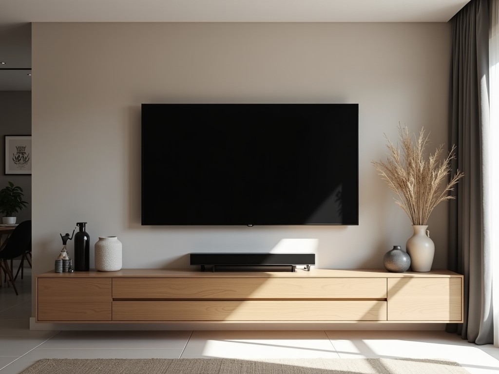
Oak Floating Tv Cabinet Unit Manufacturer
Selecting a floating TV cabinet requires understanding how material properties, joinery techniques, and wall-mounting systems interact under sustained load. Oak, as a hardwood, offers specific
- Category:
- TV Cabinet
Oak Floating TV Cabinet Unit Manufacturer
Selecting a floating TV cabinet requires understanding how material properties, joinery techniques, and wall-mounting systems interact under sustained load. Oak, as a hardwood, offers specific mechanical advantages that influence long-term performance in residential and light commercial settings.
Unlike engineered panels or softwoods, solid white oak exhibits a Janka hardness of approximately 1,360 lbf, providing resistance to denting from daily use. Its straight grain structure allows for consistent machining, which is critical when creating precision joints for concealed mounting hardware.
The dimensional stability of quarter-sawn oak minimizes seasonal movement—typically less than 0.1% across the grain—reducing stress on wall anchors and preventing joint separation over time. This characteristic is essential for floating units where load is transferred entirely to the wall interface.
Structural Design and Load Distribution
Floating cabinets rely on internal steel brackets or French cleat systems to transfer load to wall studs. The effectiveness of this system depends on the cabinet’s internal reinforcement and the compatibility between wood density and fastener pull-out resistance.
For a typical 60-inch wide oak floating TV unit supporting up to 50 kg (110 lbs) of equipment, the design incorporates 3mm thick steel brackets anchored into at least three wall studs. The bracket-to-panel interface uses 8mm diameter wood screws with a minimum embedment depth of 35mm into the oak side panels.
Internal stiffeners—often 18mm thick oak rails running perpendicular to the front panel—prevent sagging under concentrated loads from soundbars or gaming consoles. These are joined using mortise-and-tenon or pocket-hole techniques with polyurethane adhesive to accommodate minor wood movement.
Material Selection and Finishing Considerations
White oak is preferred over red oak for floating cabinets due to its tighter grain and higher resistance to moisture ingress. The tyloses in white oak block pore structures, making it less susceptible to humidity-induced swelling in environments with fluctuating RH levels.
Surface preparation involves progressive sanding from 120 to 220 grit before applying a catalyzed polyurethane finish. This two-component system provides a dry film thickness of 35–45 microns, offering abrasion resistance (Taber tester: <80 mg loss per 1,000 cycles) and protection against UV-induced yellowing.
Edge sealing is critical—end grain absorbs finish at up to 3x the rate of face grain. All exposed edges receive a sanding sealer coat prior to topcoat application to prevent uneven absorption and potential cracking at stress points.
Customization Parameters and Engineering Constraints
Standard floating TV cabinets range from 48 to 72 inches in width, 12 to 16 inches in depth, and 6 to 10 inches in height. Depth is constrained by the need to maintain a minimum 50mm clearance behind the unit for cable management and wall ventilation.
Width extensions beyond 72 inches require additional intermediate support brackets to prevent deflection. For every 6-inch increase beyond the standard span, the design adds one supplementary steel cleat rated for 25 kg point load, anchored into adjacent studs.
Height adjustments affect the center of gravity and leverage on wall anchors. Units taller than 10 inches undergo finite analysis to verify that the top panel does not induce a pull-out force exceeding 25% of the anchor’s rated capacity under dynamic load (e.g., accidental impact).
Quality Control and Manufacturing Process
Each cabinet undergoes a three-stage inspection: raw material verification, in-process joint assessment, and final load simulation. Oak blanks are checked for moisture content (target: 8% ±2%) using pin-type meters before milling to prevent post-assembly warping.
Joint integrity is tested via manual torque application—bracket screws are tightened to 3.5 Nm, and side panels are checked for any movement >0.5mm under load. Final assembly includes a 24-hour static test with 1.5x the rated weight (75 kg) to validate long-term creep resistance.
Surface finish is evaluated under 500 lux illumination for uniformity, with gloss levels measured at 60 degrees (target: 40–50 GU). Any dust inclusions or orange peel defects trigger rework before packaging.
| Parameter | Typical Value | Customization Range |
|---|---|---|
| Width | 600 mm | 480–900 mm (in 50 mm increments) |
| Depth | 140 mm | 100–200 mm |
| Height | 180 mm | 120–250 mm |
| Material | Quarter-sawn white oak | Red oak, walnut, maple (upon request) |
| Finish | Catalyzed polyurethane, matte | Gloss, satin, oil-based, stained |
| Max Load Capacity | 50 kg (evenly distributed) | Up to 100 kg with reinforced bracketing |
| Wall Mount Type | French cleat (steel) | Z-bracket, rail system, concealed plate |
Installation success depends on accurate wall assessment. The manufacturer provides a template with stud-finding guidelines and load distribution diagrams. For plasterboard walls, the system recommends using toggle bolts rated for 40 kg shear load per anchor, with a minimum of four anchors for units over 50 kg.
Lead time for standard configurations is typically 3–4 weeks after drawing approval. Custom finishes or non-standard dimensions may extend this to 6–8 weeks due to material sourcing and finish curing requirements.
Packaging includes corner protectors, edge foam, and a double-wall cardboard box rated for 30 kg stacking weight. Each unit ships with a PDF installation guide, torque specifications for fasteners, and a material safety data sheet for the finish.
For engineering teams requiring load calculations, material test reports, or BIM-ready models, technical documentation is available upon request. Contact our design support team to discuss project-specific constraints, including seismic considerations or integration with smart home infrastructure.
Request Technical Specification Sheet