Media Cabinet With Cable Management
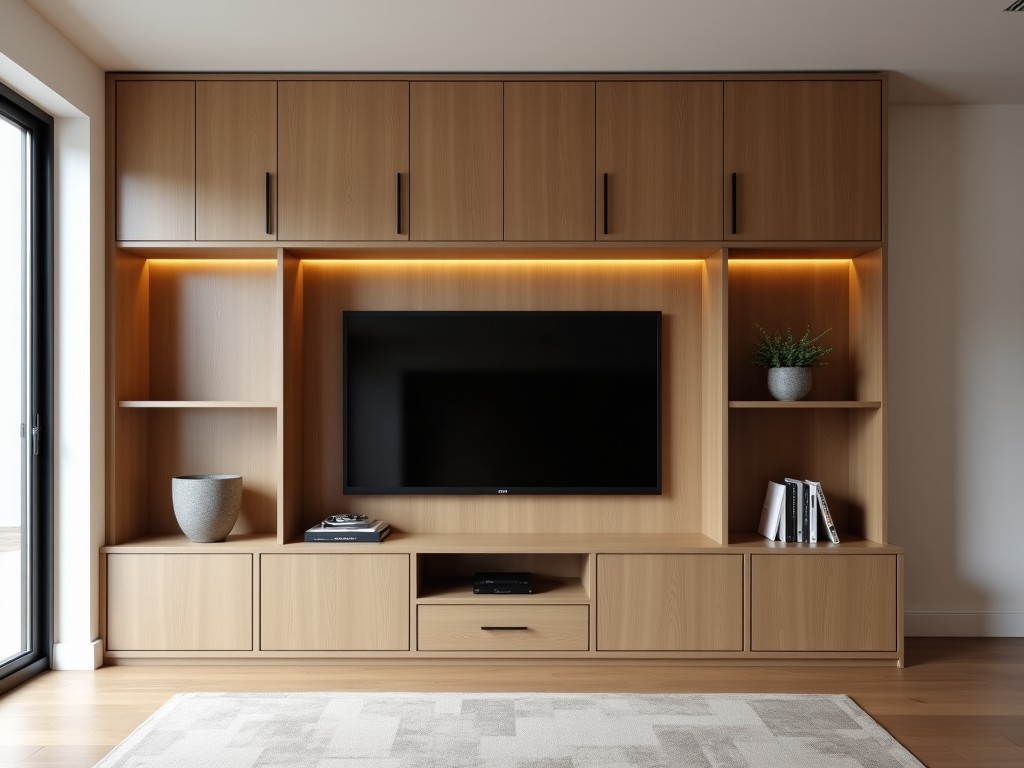
Media Cabinet With Cable Management
A media cabinet with cable management is designed to house audiovisual equipment, networking hardware, and control systems while organizing power and data cabling within a structured enclosure.
- Category:
- TV Cabinet
Media Cabinet with Integrated Cable Management
A media cabinet with cable management is designed to house audiovisual equipment, networking hardware, and control systems while organizing power and data cabling within a structured enclosure. Unlike standard storage units, these cabinets incorporate routed channels, removable panels, and strain relief features to prevent cable damage, reduce electromagnetic interference, and simplify maintenance access. The primary function is to protect sensitive electronics from dust, physical impact, and unauthorized access while ensuring optimal airflow and serviceability in fixed installations.
Structural Design and Material Construction
The cabinet frame is typically constructed from 1.2mm to 2.0mm cold-rolled steel, providing sufficient rigidity to support loads of up to 150kg depending on internal configuration. Corners are reinforced with welded gussets or bolted brackets to resist racking forces during installation or seismic events. Surface treatment includes powder coating in RAL 9005 (black) or RAL 7035 (light gray) with a minimum thickness of 80μm to ensure corrosion resistance in indoor environments. Side and rear panels are removable via concealed fasteners, allowing full access for initial setup and future modifications without damaging the finish.
Internal mounting rails are formed from the same steel stock and punched with 10mm square holes at 25mm intervals (universal pitch) to accommodate standard 19-inch rack-mounted equipment or custom brackets. Vertical cable management channels are integrated into the sidewalls, measuring 50mm in width and 40mm in depth, with snap-on covers to secure bundles of Cat6a, HDMI, or power cables. These channels align with equipment mounting points to minimize bend radius and prevent strain on connectors. Bottom and top panels include brushed nylon cable entry glands with IP54 rating to maintain dust protection while allowing routed cabling.
Cable Management System Features
The cable management system includes vertically oriented ducts with hinged or removable covers that allow technicians to add, remove, or reorganize cables without disassembling the entire cabinet. These ducts are lined with low-friction nylon inserts to reduce abrasion on cable jackets during movement. Horizontal cable managers are mounted between equipment rails at 1U or 2U intervals, featuring D-rings or spools to control slack and maintain proper bend radius for fiber optic and high-speed copper cables. All edges are deburred or rolled to eliminate sharp points that could damage insulation during installation.
Strain relief points are positioned at every cable entry and exit, using adjustable clamps that accommodate diameters from 3mm to 25mm. These clamps are isolated from the cabinet frame via rubber grommets to prevent vibration transfer. Power distribution units (PDUs) can be mounted vertically in the rear cable channel or horizontally on the base plate, with dedicated routing paths to separate low-voltage signal cables from AC power lines, reducing inductive coupling. Grounding points are welded to the frame at multiple locations, equipped with M6 studs and star washers to ensure low-impedance bonding for safety and EMC compliance.
Thermal Management and Accessibility
Passive cooling is achieved through strategically placed ventilation zones: perforated sections in the top panel (minimum 60% open area) and filtered intake vents in the bottom front door. Optional fan trays can be installed in the upper rear section, providing up to 100 CFM of airflow with PWM speed control based on internal temperature sensors. Filter media is replaceable from the front without tools, rated for MERV 8 efficiency to capture particulates while maintaining pressure drop below 15 Pa at nominal flow. Thermal modeling indicates that a fully loaded 42U cabinet with 800W dissipation maintains inlet-to-outlet ΔT under 12°C when ventilation is unobstructed.
Accessibility is enhanced through removable side panels, rear access doors with swing-out hinges, and front doors equipped with 180-degree hinges and recessed handles. Locking mechanisms include cam locks or electronic keypads with audit trail capability, depending on security requirements. Interior lighting options consist of LED strips activated by door switches, providing 200 lux illumination at work surfaces. All moving parts are rated for 10,000 cycles minimum, ensuring longevity in high-traffic environments such as control rooms or broadcast facilities.
Typical Applications in Professional Environments
Media cabinets with cable management are commonly installed in broadcast studios, live event production trucks, corporate presentation rooms, and command-and-control centers where multiple signal sources, processors, and displays must be interconnected reliably. In broadcast environments, they house video routers, audio mixers, and format converters, with cable routing designed to maintain signal integrity over long runs by minimizing proximity to power transformers and motor drives. The shielding effectiveness of the steel enclosure provides approximately 40 dB of attenuation for electromagnetic fields below 1 GHz, protecting sensitive analog and digital signals from external interference.
In corporate settings, these cabinets support video conferencing systems, digital signage controllers, and wireless presentation gateways. The organized cabling reduces mean time to repair (MTTR) by allowing technicians to trace and replace faults without tracing through tangled bundles. Educational institutions use them in lecture halls to centralize AV switching, streaming encoders, and assistive listening systems, where the locking mechanism prevents tampering by unauthorized personnel. Industrial applications include machine vision inspection systems, where the cabinet protects industrial PCs and frame grabbers from coolant mist and particulate accumulation while maintaining Ethernet and USB 3.0 connectivity to cameras and lighting units.
Customization Options and Configuration Logic
Standard heights range from 12U to 48U (1U = 44.45mm), with widths of 600mm or 800mm and depths of 600mm, 800mm, or 1000mm to accommodate varying equipment profiles. Internal equipment depth is reduced by 50mm to 100mm due to cable management channels, so actual usable space must account for this offset when selecting servers, amplifiers, or chassis with rear-mounted connectors. Custom cutouts can be provided in side or top panels for specialized cooling ducts, waveguide feeds, or fiber optic penetrations, with edge sealing to maintain IP rating.
Finish options include textured powder coat for scratch resistance, smooth gloss for easy cleaning, or anti-static coatings in environments sensitive to electrostatic discharge. Interior surfaces can be lined with conductive foam or copper tape to create a Faraday cage effect for RF shielding applications. Lock types range from keyed alike for convenience in multi-cabinet deployments to electronic access control integration with building management systems. Cable entry points can be relocated or resized based on conduit size or tray layout, with corresponding adjustments to internal channel alignment.
| Parameter | Typical Range | Notes |
|---|---|---|
| External Height (42U) | 2000mm | Includes levelling feet and top panel |
| Internal Usable Width | 482.6mm (19") | Standard rack width |
| Cable Duct Cross-Section | 50mm W × 40mm D | With snap-on cover |
| Static Load Capacity | 150kg | Evenly distributed, welded frame |
| Ventilation Open Area (Top) | ≥60% | Perforated or louvered |
| Power Cord Entry Diameter | 10mm–25mm | Adjustable strain relief clamps |
| Surface Finish Thickness | 80μm minimum | Powder coating, RAL 9005 or 7035 |
Quality Assurance and Manufacturing Considerations
Manufacturing begins with CNC punching and laser cutting of steel sheets to ensure dimensional accuracy within ±0.5mm for hole patterns and cutouts. Bent sections are formed using precision press brakes with tonnage monitoring to maintain consistent bend angles and springback compensation. Welding is performed using robotic MIG systems for consistent penetration, followed by manual touch-up in inaccessible areas. All welds undergo visual inspection per ASTM E186, with critical joints subjected to dye penetrant testing to detect subsurface flaws.
Powder coating is applied in an automated booth with electrostatic charging, followed by curing at 180°C for 20 minutes to achieve full cross-linkage. Film thickness is measured using magnetic induction gauges at five points per panel, with acceptance criteria of 70μm minimum and 120μm maximum. After coating, cabinets undergo assembly of hardware, including installation of cable management components, hinges, locks, and grounding kits. Final inspection includes verification of door alignment (gap uniformity <1.5mm), lock operation, and electrical continuity of grounding points (resistance <0.1Ω to frame). Packaging uses corrugated cardboard with edge protectors and plastic corner guards, secured with PET straps to withstand vertical drops of 760mm during handling.