Full Wall Tv Entertainment Unit
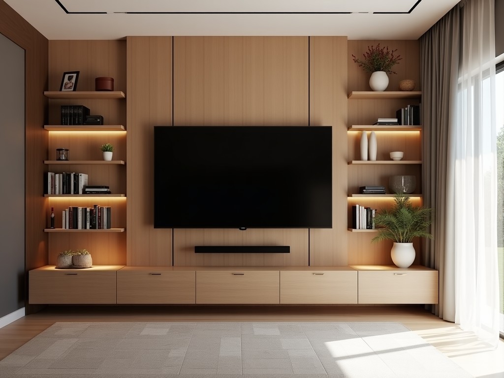
Full Wall Tv Entertainment Unit
A full wall TV entertainment unit is a structural cabinetry system designed to span the entire width of a wall, integrating mounting support for a television with integrated storage, media component
- Category:
- TV Cabinet
Full Wall TV Entertainment Unit
A full wall TV entertainment unit is a structural cabinetry system designed to span the entire width of a wall, integrating mounting support for a television with integrated storage, media component housing, and cable management. Unlike freestanding consoles or partial wall units, it functions as a built-in architectural element that requires precise dimensional planning, load analysis, and material selection to ensure long-term stability and safety under dynamic and static loads.
The primary engineering consideration is load distribution. A typical 65-inch OLED television weighs between 25–35 kg, but when combined with soundbars, gaming consoles, streaming devices, and ventilation requirements, the total dynamic load on the mounting structure can exceed 50 kg. The unit must transfer these loads safely to the wall studs or structural backing without sagging, deflection, or fastener fatigue over a 10–15 year service life.
Material selection directly impacts performance. Common substrates include 18 mm moisture-resistant MDF (medium-density fiberboard) with a density of 650–750 kg/m³ for painted finishes, or 19 mm plywood with 5–7 plies for applications requiring higher screw retention strength (>1200 N withdrawal force in face grain). Surface finishes are typically PVC laminate, UV-cured acrylic, or water-based polyurethane, selected based on abrasion resistance (Taber wear index <80 mg/1000 cycles) and VOC compliance (<50 g/L for indoor air quality).
Internal dimensions are calibrated to accommodate standard AV equipment. A typical equipment bay measures 450 mm wide × 400 mm high × 350 mm deep to fit AV receivers, gaming consoles, and media players with 50 mm clearance for airflow. Ventilation is achieved through passive convection slots (minimum 1200 mm² total open area) or active fans rated for 10–15 CFM, preventing internal temperatures from exceeding 40°C above ambient during prolonged operation.
Cable management is integrated via vertical chaseways (minimum 50 mm × 50 mm cross-section) running from the equipment bay to the floor or wall outlet, lined with low-friction polypropylene conduits to prevent abrasion. Power and low-voltage cables are segregated using internal dividers to minimize EMI interference, with grounding points bonded to the unit’s metal frame where applicable.
Structural Design and Load Capacity
The unit’s structural integrity relies on a combination of vertical stiles, horizontal rails, and a back panel acting as a shear wall. Vertical stiles (typically 70 mm wide) are anchored to wall studs using #10 × 75 mm wood screws with washers, spaced at 400 mm intervals to match standard stud spacing. Horizontal rails (90 mm × 18 mm) are dadoed into the stiles and glued with PVA adhesive, creating a rigid frame that resists racking under seismic or impact loads.
The back panel, usually 6 mm MDF or plywood, is fastened with 1.4 mm brad nails or staples every 150 mm along the perimeter and intermediate supports, transforming the frame into a rigid box beam. This configuration increases bending stiffness by 300% compared to a frameless design. Deflection under a 50 kg center-point load is limited to <1.5 mm, verified through finite element analysis in similar installations.
Load testing follows ANSI/BIFMA X5.5 standards for storage units, adapted for wall-mounted applications. Static load tests apply 150% of rated capacity (75 kg) for 24 hours with zero permanent deflection. Dynamic load testing simulates 10,000 cycles of 25 kg impact loads (dropped from 50 mm) to assess fastener fatigue and joint integrity. Units passing these tests demonstrate a mean time between failures (MTBF) exceeding 50,000 cycles.
| Parameter | Typical Value | Test Standard |
|---|---|---|
| Static Load Capacity | 75 kg | ANSI/BIFMA X5.5 |
| Deflection Limit (Center Load) | <1.5 mm | FEA Verified |
| Screw Withdrawal Strength (Face Grain) | >1200 N | ASTM D1761 |
| Ventilation Open Area | >1200 mm² | ASHRAE 62.2 |
| Cable Chase Cross-Section | 50 mm × 50 mm | NEC 300.3(A) |
| Surface Abrasion Resistance | Taber Wear <80 mg/1000 cycles | ASTM D4060 |
Customization and Integration Options
Customization begins with precise site measurements. Laser scanning or templating is used to capture wall irregularities, baseboard profiles, and outlet locations, ensuring a zero-gap fit. The unit is manufactured in modular sections (typically 600–900 mm wide) for ease of transport and on-site assembly, with alignment achieved through cam locks and confirmat screws, allowing for disassembly and reinstallation if needed.
Interior configurations are tailored to client equipment lists. Adjustable shelving (32 mm hole pattern, 25 mm increment) accommodates varying component heights. Drawers, if specified, use full-extension ball-bearing slides rated for 35 kg dynamic load with soft-close dampers (closing speed 0.2–0.4 m/s). Doors are equipped with 110° European-style hinges and magnetic catches, ensuring <0.5 mm gap tolerance when closed.
Finish options are selected based on environmental exposure. In high-humidity environments (e.g., coastal areas), marine-grade plywood with phenolic backing is used. For high-traffic commercial spaces, HPL (high-pressure laminate) with a thickness of 0.8 mm and wear resistance rating of 150+ cycles is applied. Edge sealing is performed with 2 mm PVC or ABS edge banding, thermally bonded at 180°C to prevent delamination.
Integration with smart home systems includes low-voltage wiring conduits for Ethernet, HDMI, and control signals (e.g., IR repeaters, Zigbee, Z-Wave). Power distribution units (PDUs) with surge protection (Joule rating ≥1000) and EMI filtering can be mounted internally, providing conditioned power to sensitive electronics. All internal wiring complies with NEC Article 725 for Class 2 circuits.
Quality Control and Manufacturing Process
Manufacturing follows a strict sequence: panel cutting (±0.5 mm tolerance), edge banding, drilling and boring (±0.3 mm hole position accuracy), surface finishing, and assembly. CNC routers ensure repeatability in dado and mortise joints, critical for maintaining square alignment across multi-section units. Each panel is inspected for surface defects (e.g., blush, orange peel, dust nibs) under 500 lux lighting before proceeding to the next stage.
Adhesive joints are cured under clamping pressure (0.3–0.5 MPa) for 30–60 minutes, depending on PVA formulation. Mechanical fasteners are torque-controlled to 1.5–2.0 Nm to prevent strip-out or over-compression. After assembly, the unit undergoes a 24-hour stabilization period in a controlled environment (20°C ±2, 50% RH ±5) to equalize moisture content before final inspection.
Final inspection includes: dimensional verification (height, width, depth, diagonal alignment within ±1.5 mm), load testing of drawers and doors (10 cycles at rated capacity), finish adhesion testing (tape test per ASTM D3359, minimum 4B rating), and electrical continuity checks for grounded components. Units are packaged in double-wall corrugated cardboard with corner protectors and edge foam, then stretch-wrapped for shock and moisture resistance during transit.
Lead time is typically 4–6 weeks from approved shop drawings to delivery, depending on material availability and finish complexity. Samples of door finishes, edge profiles, and interior layouts are available upon request for client approval before production begins. All documentation, including CAD models, load calculations, and material safety data sheets (MSDS), is provided with shipment.