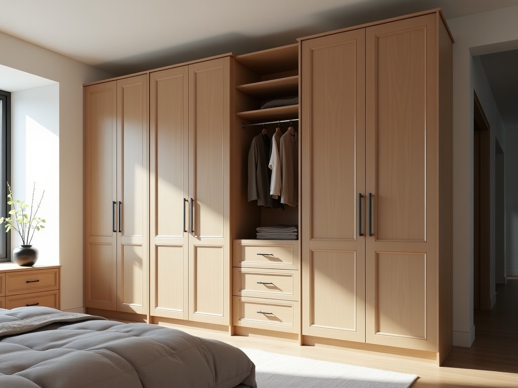
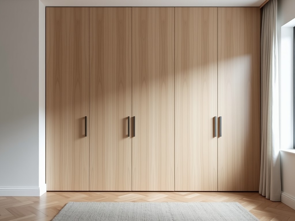
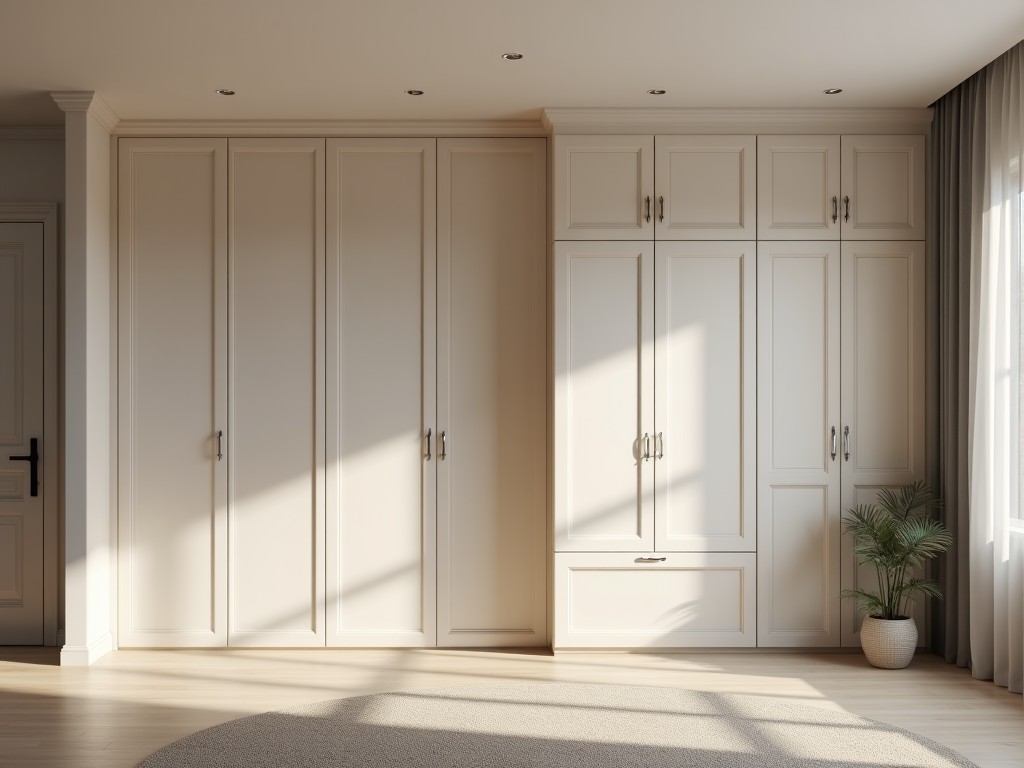
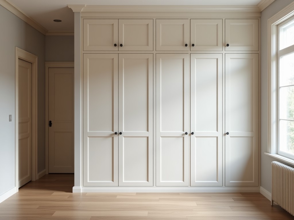
Floor To Ceiling Tv Storage Wall
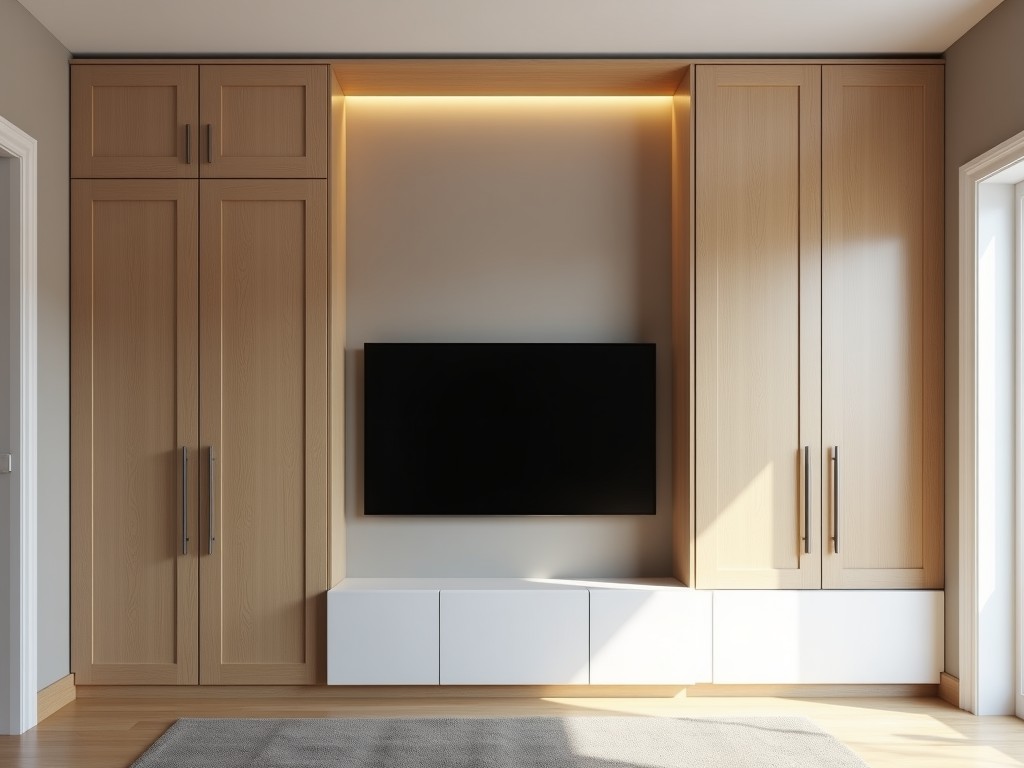
Floor To Ceiling Tv Storage Wall
Industrial environments often require secure, space-efficient solutions for mounting large displays in control rooms, training facilities, or customer showrooms. A floor-to-ceiling TV storage wall
- Category:
- TV Cabinet
Floor-to-Ceiling TV Storage Wall Systems
Industrial environments often require secure, space-efficient solutions for mounting large displays in control rooms, training facilities, or customer showrooms. A floor-to-ceiling TV storage wall integrates structural support, cable management, and equipment housing into a single vertical assembly, eliminating the need for separate shelving or wall reinforcements. This approach reduces installation complexity and minimizes floor footprint while maintaining accessibility for maintenance and upgrades.
Structural Design and Load Capacity
The system uses a steel frame anchored to both floor slab and ceiling structure, distributing vertical and lateral loads across multiple points. Frame members are typically cold-rolled steel with thicknesses ranging from 2.0mm to 3.5mm, selected based on display weight and seismic zone requirements. Each unit is engineered to support displays up to 150kg with a safety factor of 1.5, verified through finite element analysis under static and dynamic loading conditions.
Deflection limits are maintained under L/200 for vertical members and L/150 for horizontal brackets to prevent screen misalignment or stress on mounting interfaces. The frame includes adjustable leveling feet at the base and slip-fit ceiling brackets with locking pins to accommodate floor and ceiling tolerances of up to ±15mm. All connections use Grade 8.8 bolts with nylon-insert lock nuts to resist vibration loosening in industrial settings.
Cable Management and Service Access
Integrated cable channels run vertically within the frame cross-section, segregated for power, signal, and data conduits to minimize electromagnetic interference. Channel cross-sections are 50mm x 30mm with removable covers secured by quarter-turn fasteners, allowing tool-free access for rewiring or troubleshooting. Bend radii inside channels exceed 40mm to prevent cable damage during installation or flexing.
Rear access panels provide direct reach to terminal blocks, power distribution units, and media players mounted behind the display. Panels are hinged with captive screws and include gaskets to maintain dust resistance in workshop environments. Optional lockable doors are available for security-sensitive installations, featuring keyed alike cylinders and anti-tamper hinges.
Material Options and Surface Finishes
Frame components are available in hot-dip galvanized steel (Z275 coating) for corrosion resistance in humid or chemically exposed areas, or powder-coated finishes in RAL 9005 (black) or RAL 7035 (light gray) for aesthetic integration. Powder coating thickness averages 80±15μm with adhesion tested per ASTM D3359 Method B. For cleanroom or food-grade applications, 304 stainless steel frames with No. 4 brushed finish are offered upon request.
Display mounting brackets use stamped steel with welded reinforcement gussets and feature VESA-compatible hole patterns (200x200mm to 800x400mm) with ±10mm lateral and ±5mm vertical adjustment. Bracket surfaces are zinc-plated and sealed with clear trivalent chromium passivate to resist white rust. All fasteners contacting the display are coated with nylon patches to prevent marring of bezel surfaces.
Typical Configuration Table
| Parameter | Typical Value | Notes |
|---|---|---|
| Maximum Display Weight | 150 kg | Per mounting pair; higher capacities available |
| Frame Depth | 120 mm | Includes cable channel and rear clearance |
| Height Range | 2200–3000 mm | Customizable in 50mm increments |
| Adjustment Range (Vertical) | ±25 mm | Via slotted ceiling brackets |
| Cable Channel Fill Capacity | 40% cross-section | Per NEC guidelines for power/signal separation |
| Surface Finish Options | Galvanized, Powder Coat, 304 SS | Custom colors available |
Applications in Industrial Settings
In manufacturing control rooms, these walls support real-time monitoring displays for SCADA systems, allowing operators to view process data without obstructing console workspace. The vertical orientation preserves sightlines across the room while keeping CPUs, switches, and UPS units housed securely at base level, reducing cable clutter and trip hazards.
For training centers and technical schools, the system enables quick reconfiguration of display arrays for different class sizes or equipment demonstrations. Movable versions with lockable casters and floor anchors allow temporary deployment in multipurpose halls, with setup times under 30 minutes by two technicians.
In customer-facing environments such as showrooms or lobbies, the clean lines and concealed cabling enhance professional presentation while protecting AV equipment from unauthorized access or accidental damage. The modular design allows integration with existing architectural features like columns or raised floors without requiring structural modifications.
Quality Control and Testing
Each unit undergoes dimensional verification of critical interfaces using coordinate measuring machines (CMM) with tolerances held to ±0.5mm for mounting hole patterns and ±1.0mm for overall height. Load testing applies 125% of rated capacity for 10 minutes with deflection measured at three points using laser dial indicators. Residual deformation must remain under 0.25mm after unloading.
Finish quality is assessed via cross-hatch adhesion testing (ASTM D3359) and salt spray exposure (ASTM B117) for coated samples, with 500-hour duration as standard for industrial grades. Electrical continuity of grounding paths is verified with a micro-ohmmeter, requiring resistance under 0.1Ω between frame and ground terminal. All test records are retained for traceability and linked to serial numbers.
For project-specific configurations, load calculations, or integration with existing infrastructure, contact our engineering team to discuss requirements. Provide display dimensions, weight, mounting pattern, and site height for a detailed quotation and layout review.