Feature Wall With Fireplace And Tv
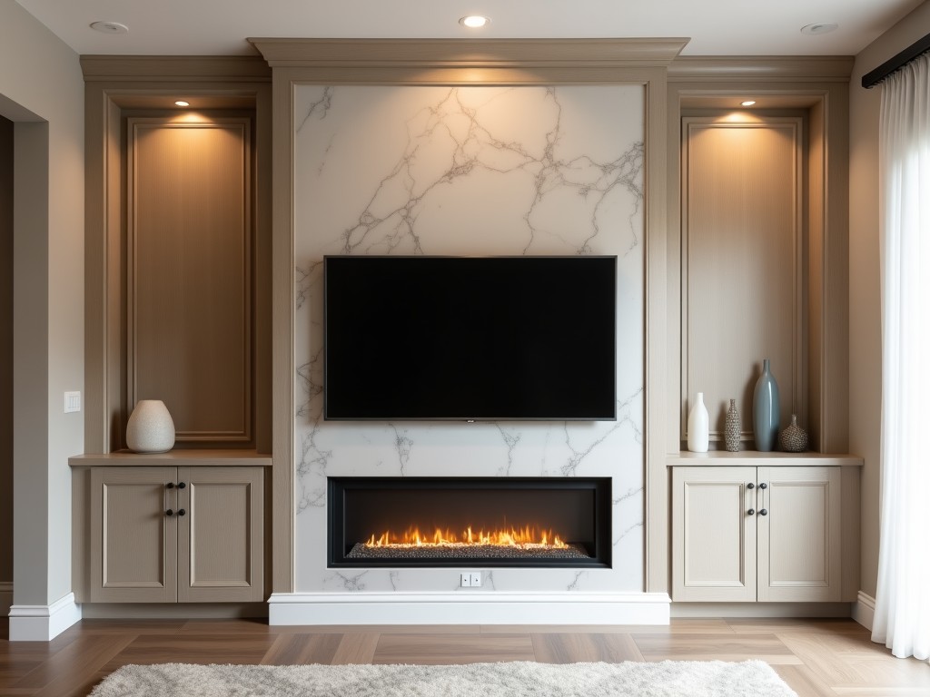
Feature Wall With Fireplace And Tv
A feature wall combining a fireplace and television requires precise engineering to manage thermal loads, structural support, and visual alignment. This integration demands coordinated design between
- Category:
- TV Cabinet
Feature Wall with Fireplace and TV Integration
A feature wall combining a fireplace and television requires precise engineering to manage thermal loads, structural support, and visual alignment. This integration demands coordinated design between heating, electrical, and mounting systems to ensure safety, functionality, and long-term durability in commercial and residential installations.
Thermal Management Design
Fireplaces generate radiant and convective heat that can damage electronic components if not properly mitigated. Minimum clearance distances between the fireplace opening and TV mounting surface must comply with manufacturer specifications, typically ranging from 12 to 24 inches depending on fuel type and BTU output. Heat deflectors or mantels are often required to redirect airflow upward and away from the display.
Thermal barriers such as calcium silicate boards or fiber-reinforced cement sheets are installed behind the TV mount to limit surface temperature rise. These materials maintain structural integrity at sustained temperatures exceeding 150°C and reduce conductive heat transfer to the wall cavity. Surface temperature monitoring during operation confirms compliance with IEC 60950-1 or UL 62368-1 safety limits for electronic equipment.
Structural Load Considerations
The combined weight of a fireplace insert, TV, and mounting hardware imposes significant static and dynamic loads on the feature wall. A typical 65-inch LED TV weighs 25–35 kg, while a built-in gas fireplace can exceed 150 kg. The wall assembly must transfer these loads to floor joists or load-bearing studs through reinforced framing.
Vertical studs are doubled or supplemented with steel brackets at mounting points to prevent sagging under sustained load. Horizontal blocking between studs provides lateral rigidity and anchor points for TV mounts. Load calculations follow ASCE 7 standards, accounting for live loads from maintenance access and potential seismic zones in commercial applications.
Electrical and Cable Management
Power and signal cables for the TV must be routed through fire-rated channels or conduits to maintain wall assembly fire resistance ratings. Low-voltage HDMI, Ethernet, and audio cables are separated from AC power lines by at least 50 mm to prevent electromagnetic interference. Service loops are included at both ends to accommodate future upgrades.
Recessed power outlets and AV plates are installed behind the TV location at heights that align with VESA mounting patterns. These fixtures use shallow-depth electrical boxes to minimize wall penetration while meeting NEC Article 314 requirements for box fill and spacing. Surge protection is recommended at the point of entry to safeguard sensitive electronics.
Material Compatibility and Finishing
Non-combustible finishes such as porcelain tile, natural stone, or metal panels are required within the fireplace clearance zone as defined by local building codes (e.g., IRC R1006). Combustible materials like wood or plywood must be kept beyond the specified distance unless protected with approved thermal barriers.
The TV mounting surface benefits from a smooth, flat substrate such as gypsum board with skim coat finish to ensure even contact with the mount’s backing plate. Texture or protrusions exceeding 1 mm can create air gaps that reduce holding strength and increase vibration transmission. Surface flatness is verified using a straight edge and feeler gauge during installation.
Typical Configuration Values
| Parameter | Typical Value | Notes |
|---|---|---|
| Minimum Fireplace-to-TV Clearance | 150–250 mm | Depends on fireplace BTU and mantel depth |
| TV Mount Load Capacity | ≥ 50 kg | Includes safety factor of 1.5x static load |
| Cable Conduit Diameter | 25–32 mm | Accommodates power + 2x HDMI + Ethernet |
| Wall Stud Reinforcement | Double 2x6 or equivalent | At mount and fireplace support points |
| Surface Temperature Limit (TV Zone) | ≤ 40°C rise | Measured at rear of TV during operation |
Customization and Project Integration
Each feature wall assembly is engineered based on site-specific conditions including fireplace model, TV dimensions, wall construction type, and local code jurisdictions. Design inputs required for quotation include fireplace clearances from the manufacturer’s installation manual, TV VESA pattern and weight, stud spacing, and finish material specifications.
Modular framing kits allow for off-site pre-assembly of load-bearing frames and cable chases, reducing on-site labor and alignment errors. These kits are labeled for specific fireplace-TV combinations and include thermal barrier cutouts, mounting brackets, and conduit pathways. Final finishing is completed on-site to match surrounding walls.
To initiate a technical review or request a project-specific configuration, contact our engineering team. Provide your fireplace and TV model numbers, wall cross-section details, and intended finish materials for a detailed feasibility assessment and component specification.
For inquiries regarding technical specifications, customization, or installation guidance, visit our contact page.