China Tv Hidden Wall Cabinet
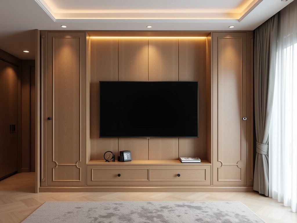
China Tv Hidden Wall Cabinet
A TV hidden wall cabinet integrates a television into a wall-mounted enclosure that conceals the screen when not in use. This solution addresses space optimization, visual clutter reduction, and
- Category:
- TV Cabinet
China TV Hidden Wall Cabinet
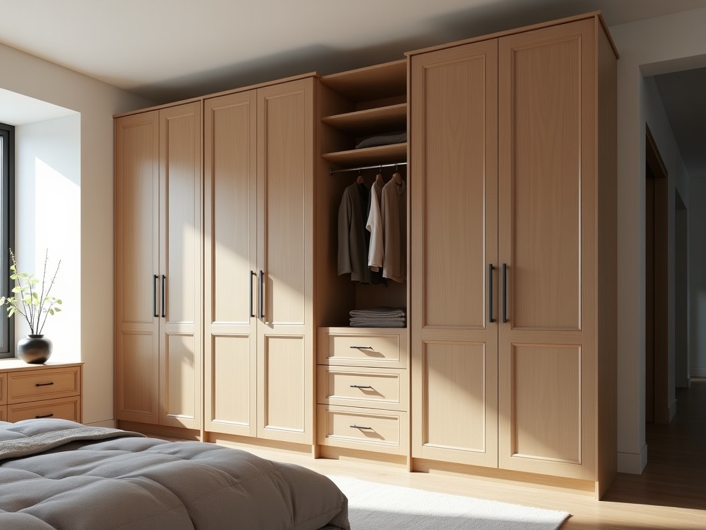
A TV hidden wall cabinet integrates a television into a wall-mounted enclosure that conceals the screen when not in use. This solution addresses space optimization, visual clutter reduction, and environmental protection in commercial and industrial settings such as control rooms, conference facilities, medical imaging areas, and retail display environments. The mechanism typically employs motorized or manual lift systems to retract or elevate the display behind a flush-mounted panel, maintaining a clean architectural line.
Core Design Considerations
Effective hidden cabinet design begins with precise dimensional alignment between the TV specifications and the cabinet cavity. Critical factors include screen diagonal, VESA mounting pattern, depth clearance for cabling and ventilation, and operational stroke length of the lift mechanism. Manufacturers calculate minimum internal dimensions by adding 50mm to the TV’s width and height for airflow and service access, while depth must accommodate the TV’s thickness plus 30mm for mechanism housing and wiring bends. Misalignment risks thermal buildup, mechanical binding, or insufficient cable service loops.
Material selection directly impacts durability, weight, and finish quality. Common substrates include 18mm MDF with PVC laminate for cost-sensitive applications, 12mm tempered glass for high-end visual transparency when closed, and 1.2mm cold-rolled steel for industrial environments requiring impact resistance. Surface finishes undergo abrasion testing (ASTM D4060) to ensure scratch resistance under frequent panel operation. Edge sealing with polyurethane prevents moisture ingress in humid environments like food processing areas.
Mechanism Types and Performance
Lift mechanisms fall into three primary categories: scissor lift, vertical screw drive, and belt-driven linear actuator. Scissor lifts offer high load capacity (up to 150kg) but require greater lateral space; screw drives provide precise positional control (±2mm repeatability) ideal for flush-fit applications; belt drives deliver quiet operation (<45dB) suited for noise-sensitive areas like audiovisual studios. All industrial-grade units incorporate overload protection, emergency stop integration, and positional feedback via Hall effect sensors.
Motor specifications typically range from 24V DC, 60W to 120W depending on TV weight and stroke speed requirements. Standard operational speed is 25–35mm/s, balancing safety and usability. Duty cycle ratings (S3 25%) indicate suitability for intermittent use in meeting rooms; continuous-duty variants (S1) are specified for control rooms with frequent access. Backlash compensation in gearboxes minimizes panel drift over time, maintaining alignment tolerance within 1mm after 10,000 cycles.
Environmental and Safety Compliance
Cabinets intended for industrial use must comply with relevant safety standards. Electrical systems follow IEC 60335-2-97 for motorized furniture, incorporating double insulation, earth leakage protection (<30mA), and low-voltage control circuits (24V DC). Mechanical safety includes anti-pinch sensors that halt motion upon detecting 15N of resistance, and mechanical brakes that hold position during power failure. Surface temperatures of motors and drives remain below 60°C under continuous operation, verified via IEC 60601-1-11 thermal testing.
Ingress protection (IP) ratings define suitability for specific environments. IP20 is standard for dry indoor offices; IP54 resists dust and splashing water in workshops; IP65 is required for washdown areas in pharmaceutical or food production. Sealing methods include gasketed panel edges, conduit-sealed cable entries, and conformal coating on PCB assemblies. Corrosion resistance is evaluated via salt spray testing (ASTM B117) for 240 hours in coastal or chemical-exposed installations.
Customization and Integration
Customization begins with client-provided TV model data or schematic drawings. Engineers derive cavity dimensions, mechanism stroke, and mounting plate geometry from these inputs. Cable management systems include segmented drag chains (e.g., igus® e-chains) with internal separation for power, HDMI, and control wires, rated for 10,000 flex cycles. Ventilation is addressed through passive convection vents (min. 200cm² open area) or active 12V DC fans (40CFM) with PWM speed control triggered by internal temperature sensors (>45°C).
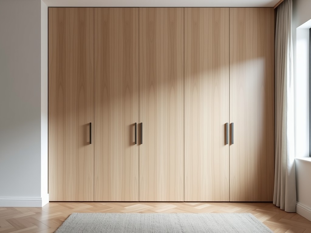
Panel finishes can be customized to match surrounding architecture using veneers, powder-coated metals, or back-painted glass. Options include wood grain laminates (Oak, Walnut), RAL-class powder coats (e.g., RAL 9005 Jet Black), or low-iron glass with ceramic frit printing for translucent effects. Integration with building management systems is achievable via dry-contact relays or RS-485 Modbus interfaces, enabling synchronized operation with lighting, HVAC, or access control systems.
Quality Control and Testing
Factory acceptance testing (FAT) verifies operational reliability before shipment. Each unit undergoes 50 full extension-retraction cycles under nominal load, with positional accuracy checked at 25%, 50%, and 75% stroke points using laser displacement sensors. Audible noise is measured at 1m distance; units exceeding 50dB(A) are rejected. Electrical safety includes hipot testing (1.5kV AC for 1s) and insulation resistance (>50MΩ at 500V DC).
Long-term durability is assessed via accelerated life testing: 10,000 cycles at 40°C and 85% relative humidity simulates 5 years of daily use. Post-test inspection checks for mechanism wear, panel delamination, and fastener torque retention (>80% of initial spec). Paint adhesion is validated via cross-hatch test (ASTM D3359) requiring 4B or better rating. All test results are documented in a traceable batch report linked to serial number.
| Parameter | Typical Range | Notes |
|---|---|---|
| TV Size Compatibility | 32" – 86" diagonal | Limited by mechanism load and cavity depth | Load Capacity | 50kg – 150kg | Dependent on lift type and motor rating |
| Stroke Speed | 20mm/s – 40mm/s | Adjustable via motor PWM |
| Positional Repeatability | ±1mm – ±3mm | Screw drives offer highest precision |
| Noise Level | <45dB(A) at 1m | Belt drives typically quietest |
| IP Rating | IP20 – IP65 | Customizable per environment |
| Power Supply | 100–240V AC, 50/60Hz | Internal DC conversion to 24V |
| Control Options | IR, RF, RS-485, Dry Contact | Optional wall switch or app |
Applications in Industrial and Commercial Settings
In broadcast control rooms, hidden cabinets protect monitors from dust and accidental impact while maintaining ergonomic viewing angles. The retractable screen allows operators to access underlying control panels or communication gear when the TV is stowed, improving workspace efficiency. Motorized lifts synchronized with camera switches enable automatic display activation during live feeds, reducing manual intervention.
Medical imaging facilities use IP65-rated cabinets to house diagnostic displays in sterilizable zones. The sealed construction withstands daily cleaning with hydrogen peroxide vapors and alkaline detergents without degradation. When not in use, the concealed screen minimizes visual distraction in procedure rooms, supporting focus on patient-facing equipment. Cable routing through sealed conduits prevents contamination pathways.
Retail environments deploy hidden cabinets for dynamic window displays. During business hours, the TV rises to showcase promotions; after hours, it retracts to reveal architectural details or security panels. This dual functionality reduces the need for separate display and enclosure systems, lowering installation complexity. Integration with ambient light sensors adjusts screen brightness automatically, extending panel lifespan and reducing energy use.
Ordering and Project Engagement
To initiate a quotation, clients should provide: exact TV model number (including year), desired operation mode (motorized/manual), preferred panel finish material, control interface requirements, and installation environment (indoor/outdoor, humidity, temperature range). Structural details such as wall stud spacing, load-bearing capacity, and access for rear service are also required to confirm mounting feasibility and mechanism selection.
Lead times typically range from 4–6 weeks for standard configurations, extending to 8–10 weeks for fully customized finishes or integrated control systems. Shipping is conducted via palletized crates with internal bracing and shock indicators to detect mishandling. Installation guides include electrical schematics, mechanical clearance diagrams, and commissioning checklists for third-party integrators. After-sales support includes spare part availability for motors, sensors, and control boards for a minimum of 7 years.
For technical consultation or to submit project specifications for evaluation, contact our engineering team. Provide the information outlined above to receive a detailed feasibility assessment, including load calculations, mechanism recommendations, and compliance documentation relevant to your installation site.