China Aluminum Tv Wall Unit
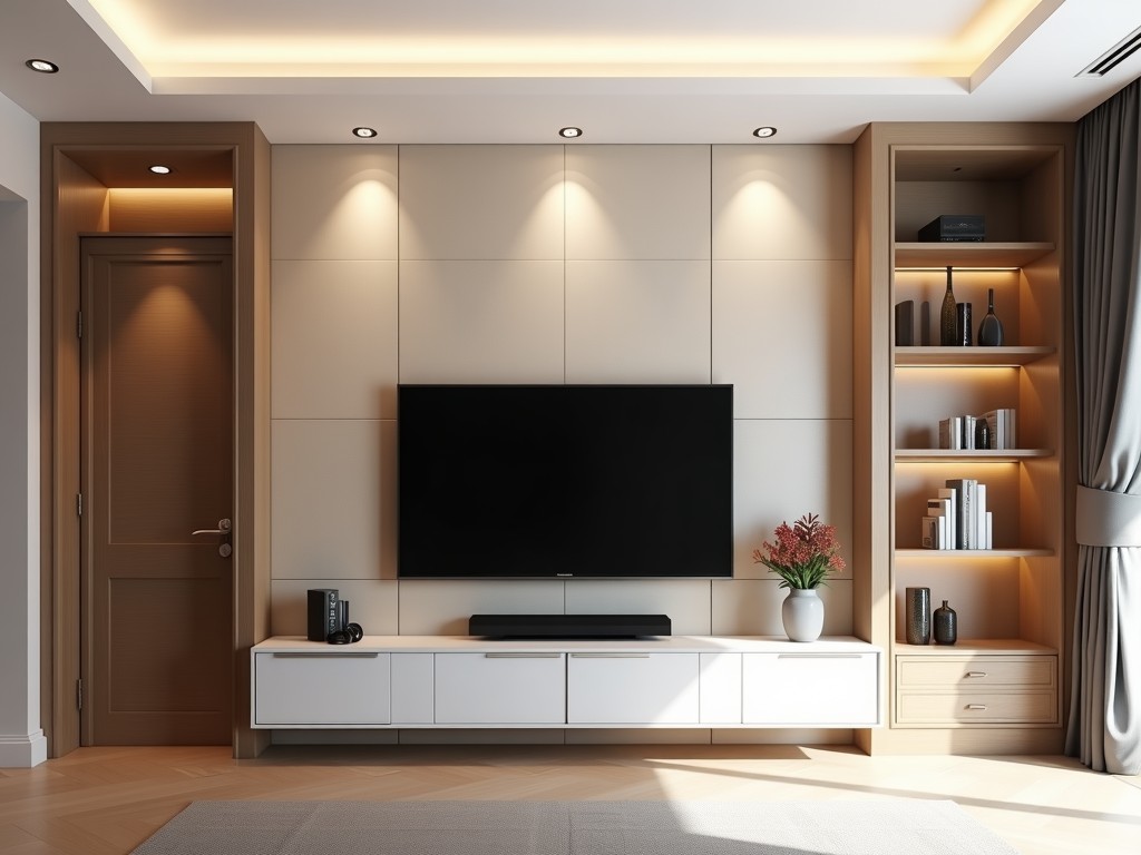
China Aluminum Tv Wall Unit
Aluminum TV wall units from Chinese manufacturers provide a structural mounting solution for flat-panel displays in commercial, industrial, and institutional environments. These units are engineered
- Category:
- TV Cabinet
China Aluminum TV Wall Unit
Aluminum TV wall units from Chinese manufacturers provide a structural mounting solution for flat-panel displays in commercial, industrial, and institutional environments. These units are engineered to support specified load capacities while maintaining dimensional stability under varying environmental conditions. Material selection, extrusion tolerances, and connection methods directly influence long-term performance and safety compliance. Understanding these technical factors enables procurement teams to evaluate suitability beyond superficial appearance.
Typical applications include control rooms, broadcasting studios, transportation hubs, and manufacturing facilities where displays require secure, vibration-resistant mounting. Unlike residential mounts, industrial units must accommodate dynamic loads, thermal cycling, electromagnetic interference considerations, and integration with cable management systems. The aluminum construction offers a favorable strength-to-weight ratio compared to steel alternatives, reducing structural load on building supports while resisting corrosion in humid or chemically exposed environments.
Manufacturing processes involve precision extrusion of 6063-T5 or 6061-T6 aluminum alloys, followed by CNC machining for interface surfaces and powder coating or anodizing for surface protection. Tolerance control on mating surfaces is critical to prevent display misalignment or stress concentration. Load ratings are determined through finite element analysis and validated via static testing per IEC 62368-1 or equivalent safety standards, with safety factors typically ranging from 3:1 to 5:1 depending on application risk level.
Key Technical Characteristics
Load capacity is defined by the maximum static weight the unit can support without permanent deformation, typically ranging from 50 kg to 200 kg per mounting point depending on extrusion profile and reinforcement design. Dynamic load ratings, which account for vibration and shock, are generally 30-50% lower than static values and must be specified for mobile or high-vibration environments. Deflection limits are engineered to remain under 1 mm at maximum load to prevent visual distortion or edge stress on the display panel.
Thermal expansion coefficients of aluminum alloys (approximately 23.5 µm/m·°C) necessitate expansion joints or sliding interfaces in long-span units to prevent buckling under temperature fluctuations. Surface treatments such as anodizing (Type II, 10-15 µm thickness) or powder coating (60-80 µm) provide corrosion resistance suitable for indoor industrial environments; marine or coastal applications may require additional sealing or higher-grade alloys like 5052-H32. Electrical continuity is maintained through conductive coatings or bonding straps where grounding is required for EMI shielding.
Modular design principles allow for horizontal and vertical expansion using standardized T-slot or dovetail interfaces, enabling future reconfiguration without unit replacement. Cable management channels are integrated into the extrusion profile with removable covers, maintaining IP20 ingress protection while facilitating service access. Adjustment mechanisms—such as sliding brackets, tilt arms, or height-adjustable pillars—use hardened steel inserts or nylon bushings to minimize wear and maintain positional accuracy over thousands of adjustment cycles.
Material and Finish Options
| Characteristic | Typical Range / Options | Technical Implication |
|---|---|---|
| Aluminum Alloy | 6063-T5, 6061-T6, 5052-H32 | Strength, corrosion resistance, weldability |
| Surface Finish | Clear anodize, bronze anodize, black powder coat, custom RAL | Corrosion protection, emissivity, visual integration |
| Profile Thickness | 2.0 mm to 6.0 mm wall thickness | Bending rigidity, load span capability |
| Length Tolerance | ±0.5 mm/m (extrusion), ±0.2 mm (machined) | Alignment accuracy, gap control |
| Edge Treatment | Deburred, radius 0.5-2.0 mm, chamfered | Safety, cable protection, seal compatibility |
Alloy selection directly affects the unit’s strength-to-weight ratio and environmental resistance. 6063-T5 offers good extrudability and adequate strength for most indoor applications, while 6061-T6 provides higher tensile strength (up to 310 MPa) for longer spans or higher load demands. 5052-H32 is preferred in environments with exposure to moisture or mild chemicals due to its superior corrosion resistance, though it is less amenable to complex extrusion profiles. Surface finish choice influences both durability and thermal management; dark anodized finishes increase emissivity, aiding passive heat dissipation from mounted equipment.
Profile geometry is optimized through finite element analysis to maximize moment of inertia while minimizing material usage. Common shapes include I-beam, box, and T-slot configurations, each suited to different loading conditions. T-slot profiles facilitate accessory mounting using standard M4-M8 T-nuts, allowing third-party components such as camera brackets, sensor mounts, or lighting fixtures to be integrated without drilling or welding. Wall thickness variations along the profile length are used to reinforce high-stress zones such as connector points or load-bearing nodes.
Dimensional tolerances are controlled per ISO 2768-m or tighter for critical interfaces. Straightness and twist tolerances are particularly important for multi-unit assemblies where cumulative deviation could lead to misalignment. Machined interfaces for display VESA plates or structural connectors are typically held to ±0.1 mm flatness and parallelism to ensure even load distribution and prevent panel stress. These precision requirements necessitate CNC machining after extrusion, which adds cost but is essential for performance-critical installations.
Design and Customization Logic
Customization begins with load case analysis: static weight, dynamic forces (vibration, seismic), thermal cycles, and environmental exposure. Engineers calculate required section modulus and deflection limits using beam theory, then select extrusion profiles that meet or exceed these values with appropriate safety factors. Connection methods—bolted, welded, or interlocking—are chosen based on serviceability needs; welded joints offer higher stiffness but limit future modification, while bolted flanges allow disassembly for maintenance or reconfiguration.
Modularity is achieved through standardized interface grids, typically 40mm or 80mm spacing, allowing accessories to be positioned at incremental points along the unit. This enables phased upgrades—such as adding soundbars, control panels, or lighting—without replacing the core structure. Adjustment mechanisms incorporate lock-to-position features using detents or friction locks to prevent drift under vibration. Linear bearings or slide rails are used in height-adjustable models, with load ratings specified for both dynamic and static conditions.
Cable management is not an afterthought but a core design parameter. Internal channels are sized based on anticipated cable bundle diameter and bend radius requirements, typically accommodating 20-50 mm diameter bundles with 10x cable diameter minimum bend radius. Separation of power and signal cables is facilitated through internal dividers or segregated channels to reduce electromagnetic interference. Service access is provided via snap-on or screw-down covers, with ingress protection rated to IP20 or higher as needed.
Thermal considerations influence both material selection and geometry. For equipment generating significant heat (e.g., amplifiers, servers), the unit may incorporate heat sink fins or thermal vias to transfer heat to the ambient air. Ventilation slots are sized using natural convection calculations, ensuring sufficient airflow without compromising structural integrity. In enclosed environments, forced air cooling may be integrated via fan mounts designed into the extrusion profile.
Quality Control and Testing
Dimensional inspection begins at raw material receipt, with extrusion lots checked for diameter, wall thickness, and straightness using calibrated gauges or laser scanners. Critical dimensions—such as VESA hole patterns, T-slot width, and mating surface flatness—are verified via CMM or optical comparators during in-process inspection. Surface finish quality is assessed for coating thickness (using eddy current or magnetic induction gauges), adhesion (cross-hatch test per ASTM D3359), and uniformity, particularly in recessed or complex geometry areas.
Mechanical validation includes static load testing at 125% of rated capacity for 10 minutes, with deflection measured via dial indicators or laser displacement sensors. Fatigue testing simulates 10,000 adjustment cycles or vibration exposure using shaker tables tuned to specific frequency spectra (e.g., 5-500 Hz for transportation environments). Torque testing on fasteners ensures clamping force remains within specified ranges after thermal cycling, preventing loosening over time. All test data is retained for traceability and linked to serial numbers or batch IDs.
Non-destructive evaluation methods such as dye penetrant inspection or ultrasonic testing are applied to welds and high-stress areas to detect subsurface flaws invisible to visual inspection. Electrical bonding continuity is verified using micro-ohm meters to ensure resistance remains below 0.1 ohms between all conductive parts and grounding points. Environmental testing includes humidity cycling (per IEC 60068-2-30) and salt spray exposure (per ASTM B117) for units intended for harsh conditions, with acceptance criteria based on visual corrosion and performance degradation thresholds.
Final assembly verification includes functional checks of all moving parts, torque validation of accessible fasteners, and visual inspection for scratches, dents, or finish defects. Packaging is designed to prevent damage during transit, using corner protectors, foam end caps, and stretch-wrapping on pallets. Unit identification labels include model number, load rating, serial number, and QR code linking to digital documentation such as installation manuals, test reports, and material certificates. This end-to-end traceability supports warranty claims and facilitates field replacements.
Applications in Industrial Environments
In broadcast control rooms, aluminum TV wall units support multi-display videowalls requiring precise alignment and minimal vibration transmission. The low mass of aluminum reduces seismic load on raised floors, while the non-magnetic property prevents interference with sensitive audio equipment. Units are often configured with lateral shift mechanisms to allow fine-tuning of display edges to within 0.5 mm, critical for seamless image blending in high-resolution setups. Integration with ambient lighting systems is achieved through T-slot mounted LED strips, controlled via the same central system as the displays.
Transportation infrastructure—such as airport control towers, train dispatch centers, and traffic management facilities—requires units that withstand continuous vibration and temperature extremes. Aluminum’s corrosion resistance performs well in environments with occasional condensation or cleaning chemical exposure. Units are frequently anchored to concrete or steel structures using isolation pads to mitigate structure-borne noise. Cable management includes strain relief blocks and grounding lugs to comply with transportation safety standards such as EN 50121 or IEC 62233.
Manufacturing and process control environments benefit from the unit’s resistance to oils, coolants, and particulate matter. Powder-coated finishes with chemical-resistant additives are used in areas near machining or welding operations. Units may include integrated sensor mounts for cameras or laser scanners, positioned using adjustable arms to maintain line of sight despite equipment movement. In cleanroom applications, smooth surfaces and minimal particle traps are prioritized, with electropolished or anodized finishes and sealed joints to meet ISO 14644-1 Class 6 or higher requirements.
Retail and exhibition spaces utilize aluminum units for their aesthetic flexibility and ease of reconfiguration. Custom powder coating in brand-specific colors allows visual integration with interior design. The modular nature enables rapid layout changes for seasonal displays or event-based installations without structural modifications. Anti-theft features such as tamper-resistant fasteners or locking mechanisms are incorporated where displays are accessible to the public. Load ratings account for dynamic forces from crowd interaction or cleaning equipment contact.
Ordering and Project Information
To initiate a quotation, provide the following technical details: display specifications (weight, dimensions, VESA pattern), mounting orientation (landscape/portrait), required adjustment ranges (tilt, swivel, height), environmental conditions (temperature range, humidity, chemical exposure), and any accessory loads (soundbars, cameras, lighting). Structural interface information—such as mounting surface type (concrete, steel stud, raised floor) and available fastening points—is essential for designing appropriate brackets or base plates. Seismic zone or vibration spectra data should be shared if applicable.
Lead times typically range from 4 to 8 weeks for standard configurations, depending on profile availability and surface finish complexity. Custom extrusions or specialized alloys may extend this timeline. Sample units are available for validation, usually supplied as single-axis or dual-display configurations to evaluate adjustment mechanisms and load behavior. Sample costs are credited toward the first production order if placed within 90 days. Shipping is managed via LCL or FCL containerized freight, with foam-protected crates and corner bracing to prevent transit damage.
Payment terms are commonly 30% T/T in advance, 70% against copy of B/L, or LC at sight for international orders. Domestic orders may accept net 30 days upon credit approval. All quotations include material certificates, test reports, and installation drawings in PDF or DWG format. Warranty periods are typically 24 months from date of shipment, covering defects in materials and workmanship under normal use conditions. Extended warranties or on-site support are available upon request for critical infrastructure projects.
For projects requiring regulatory compliance, documentation can be provided for CE marking, FCC Part 15 compliance, or UL listing where applicable. While the aluminum unit itself is a mechanical component, its integration with electronic displays may require system-level certification. Manufacturers can supply Declaration of Incorporation or component test data to support OEM certification efforts. Environmental compliance documentation, such as RoHS or REACH statements, is available for all materials and finishes used in the unit’s construction.
For technical inquiries, customization requests, or project-specific quotations, contact our engineering team to discuss your application requirements. Provide your specifications for a detailed evaluation and formal proposal.
Request Technical Quotation