Buy Backdrop Tv Wood Panel
Buy Backdrop Tv Wood Panel
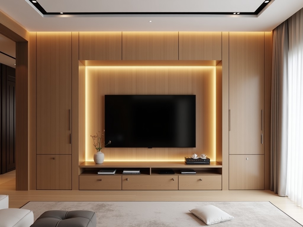
A backdrop TV wood panel integrates a television into a wall-mounted wood assembly designed for commercial and institutional environments. Unlike residential TV mounts, these systems address
- Category:
- TV Cabinet
Backdrop TV Wood Panel Systems
A backdrop TV wood panel integrates a television into a wall-mounted wood assembly designed for commercial and institutional environments. Unlike residential TV mounts, these systems address structural load distribution, thermal management, and long-term dimensional stability under variable humidity conditions. The panel functions as both a decorative finish and a load-bearing substrate, requiring precise engineering to prevent sagging, warping, or fastener fatigue over time.
Structural Design and Load Performance
The panel substrate is engineered to support the combined weight of the TV, mounting hardware, and dynamic forces from vibration or accidental impact. Calculations follow ANSI/BIFMA X5.5 standards for commercial furniture, with safety factors applied to shear and withdrawal resistance of fasteners into the wood core. Typical designs accommodate TVs up to 40 kg (88 lbs) with a maximum dynamic load of 1.5 times static weight, distributed across a minimum of four anchor points spaced no less than 300 mm apart.
Wood movement due to moisture content changes is mitigated through cross-laminated construction or stabilized core materials. Panel thickness ranges from 18 mm to 25 mm, selected based on span between supports and expected environmental fluctuations. Edge sealing and back ventilation channels reduce differential swelling, maintaining dimensional stability within ±0.5 mm over annual humidity cycles of 30% to 70% RH.
Material Selection and Finish Options
Core materials include FSC-certified hardwood plywood, engineered wood composites, or thermally modified timber, chosen for their modulus of elasticity and resistance to creep. Surface veneers are selected for abrasion resistance (Taber Test >400 cycles) and color stability under UV exposure. Finish systems use low-VOC, catalyzed polyurethanes or water-based acrylics with a dry film thickness of 40–60 μm, providing scratch resistance comparable to ISO 2815 Class 2.
Edge treatments include solid wood lipping, PVC edge banding, or laser-sealed edges to prevent moisture ingress. Panel faces may be flat, routed for shadow gaps, or textured to match architectural woodwork. Custom profiles are achievable via CNC milling with tolerances of ±0.2 mm, allowing integration with recessed lighting, cable management channels, or acoustic backing materials.
Thermal and Cable Management Integration
Heat dissipation from the TV’s rear panel is critical to prevent overheating and maintain manufacturer warranty validity. Ventilation gaps of 10–15 mm are incorporated behind the TV, aligned with the TV manufacturer’s recommended clearance. Passive convection is enhanced through vertical channels or perforated zones totaling at least 5% of the rear panel area, verified via computational fluid dynamics in prototype testing.
Cable management is addressed through molded channels, removable access panels, or flexible grommets rated for 50+ insertion cycles. Power and data conduits maintain a minimum 50 mm separation from structural fasteners to avoid electromagnetic interference. All openings are fitted with abrasion-resistant liners to protect cable jackets during installation and maintenance.
Installation and Field Adjustability
Panels are designed for direct attachment to steel studs, concrete walls, or wood blocking using through-bolts, lag screws, or chemical anchors as specified by the structural engineer. Mounting hardware includes adjustable brackets allowing ±10 mm vertical and ±5 mm lateral adjustment post-installation to compensate for wall irregularities. Leveling is verified using digital inclinometers with resolution of 0.1°.
Field modifications are accommodated through pre-drilled access points and modular infill panels. Replacement of damaged veneer sections is possible without full panel removal, using color-matched repair kits with shelf life exceeding 12 months when stored below 25°C. Maintenance access is facilitated by quick-release mechanisms requiring no specialized tools, reducing service time to under 15 minutes for routine inspections.
| Parameter | Typical Value | Notes |
|---|---|---|
| Panel Thickness | 18–25 mm | Depends on span and load |
| Max Static Load | 40 kg (88 lbs) | Safety factor 2:1 on fasteners |
| Ventilation Gap | 10–15 mm | Behind TV for thermal management |
| Finish Dry Film Thickness | 40–60 μm | UV-stabilized polyurethane |
| Adjustment Range | ±10 mm vertical, ±5 mm lateral | Post-installation compensation |
Applications in Commercial Environments
These systems are specified in corporate lobbies where aesthetic continuity with wood wall paneling is required, and the TV must appear as an integrated architectural element rather than an appended device. In healthcare waiting areas, the panel’s smooth, cleanable surface supports infection control protocols, while its non-reflective finish reduces glare under ambient lighting. Educational institutions use them in lecture halls and collaborative spaces, where resistance to impact from backpacks or equipment is essential, and the wood finish contributes to acoustic comfort by reducing reverberation compared to metal or glass alternatives.
Hospitality installations, such as hotel lobbies or conference centers, benefit from the panel’s ability to conceal wiring and mounting hardware while maintaining a premium appearance that aligns with brand standards. The modular design allows for phased installation during renovation projects, minimizing downtime. Retail environments utilize these panels for product displays or informational kiosks, where the wood finish conveys warmth and approachability, contrasting with the cool tones of digital screens to create balanced visual hierarchies.
Quality Control and Testing Protocols
Each panel undergoes dimensional verification using laser scanning to confirm flatness within 0.3 mm/m across the surface. Adhesion testing of veneer and finish follows ASTM D3359 Method B, with a minimum rating of 4B required for acceptance. Load testing is performed on random samples using dynamic load simulators that replicate 10,000 cycles of vibration and impact, with deflection limits set to L/200 where L is the unsupported span.
Finished panels are conditioned at 23°C and 50% RH for 48 hours prior to final inspection to stabilize moisture content. Color consistency is verified using spectrophotometry with ΔE < 1.5 between production batches. Documentation includes material traceability certificates, finish batch records, and test reports available upon request. Packaging includes corner protectors, stretch wrapping, and humidity indicator cards to monitor transit conditions, with units stacked no higher than 1.2 m to prevent deformation.