Built In Tv Wall Cabinet
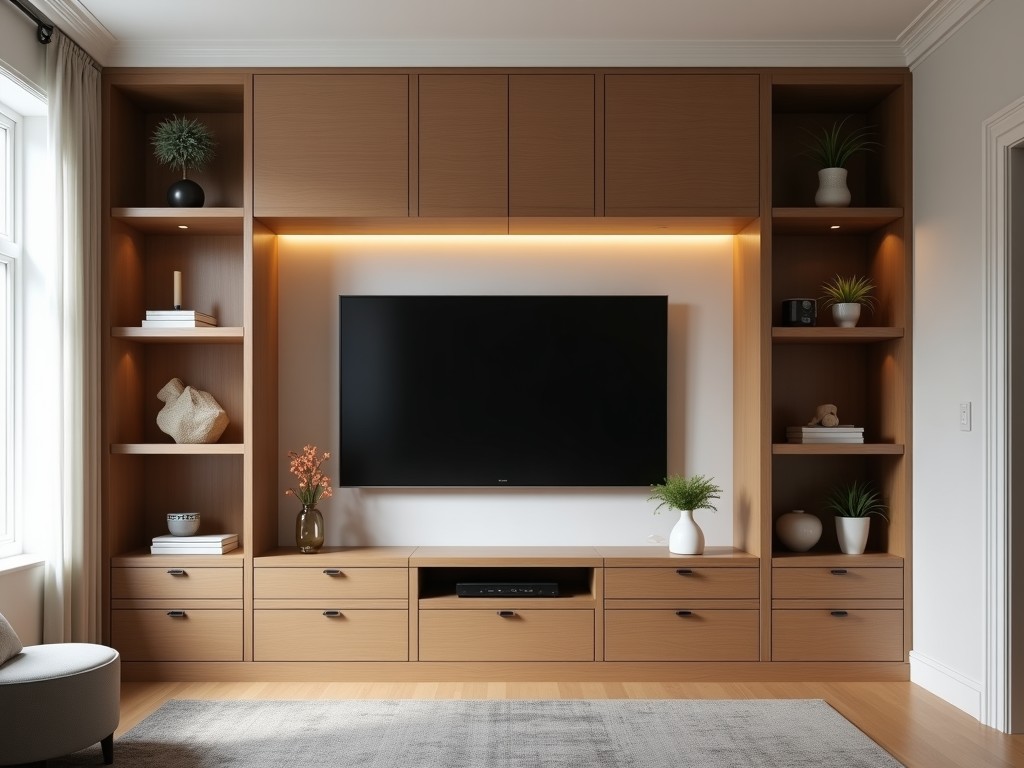
Built In Tv Wall Cabinet
A built-in TV wall cabinet is a recessed or semi-recessed enclosure designed to house a television and associated audiovisual equipment within a wall structure. Unlike freestanding media consoles,
- Category:
- TV Cabinet
Built-In TV Wall Cabinet: Technical Specifications and Applications
A built-in TV wall cabinet is a recessed or semi-recessed enclosure designed to house a television and associated audiovisual equipment within a wall structure. Unlike freestanding media consoles, these cabinets are integrated during construction or renovation, providing a flush-mounted appearance that aligns with architectural surfaces. The primary function is to conceal wiring, reduce visual clutter, and protect equipment while maintaining accessibility for service and ventilation.
Industrial and commercial applications include control rooms, conference facilities, healthcare environments, and retail displays where space optimization, cable management, and equipment security are critical. The design must accommodate specific TV dimensions, ventilation requirements, and load-bearing constraints of the surrounding wall assembly.
Core Design Parameters
The cabinet’s internal dimensions are determined by the TV’s width, height, and depth, plus required clearance for airflow and cable routing. Minimum rear clearance is typically 50 mm for passive cooling, increasing to 100 mm or more for enclosed active ventilation systems. Side clearances of 25–50 mm per side allow for wiring access and thermal expansion tolerance.
Depth is constrained by wall stud spacing and structural limitations. In standard wood-frame walls (38 mm x 89 mm studs), maximum recess depth is approximately 75 mm without reinforcement. Deeper installations require furring channels, metal stud framing, or concrete/masonry cutouts with proper lintel support. Front protrusion is minimized to maintain flush alignment, usually under 10 mm for trim or door overlap.
Load capacity must support the TV’s weight plus dynamic forces from mounting hardware. A 55-inch commercial display may weigh 15–25 kg; larger formats (75–86 inch) can exceed 40 kg. Cabinet framing and fasteners are selected based on shear and tensile loads, with safety factors applied per local building codes (e.g., ASCE 7, IBC).
Material Selection and Fabrication
Common substrates include moisture-resistant MDF, plywood (birch or poplar core), and metal alloys (aluminum or steel) for high-load or fire-rated applications. MDF offers smooth finish and machinability but requires edge sealing in humid environments. Plywood provides superior screw retention and dimensional stability, particularly in load-bearing frames.
Surface finishes range from painted or veneered wood to powder-coated metal or laminate overlays. Edge treatments (PVC, wood veneer, or metal banding) prevent moisture ingress and impact damage. Interior surfaces may feature low-reflective coatings to reduce glare and cable visibility.
Fabrication tolerances are critical for flush installation. CNC routing ensures consistent dadoes, rabbets, and mounting holes within ±0.5 mm. Frame assembly uses pocket screws, cam locks, or metal brackets to maintain squareness under load. All joints are designed for disassembly to facilitate servicing without damaging surrounding finishes.
Ventilation and Thermal Management
Passive ventilation relies on convection through top and bottom grilles. Effective airflow requires unobstructed paths: intake at the bottom (min. 75% open area), exhaust at the top (min. 50% open area). Grille designs use perforated metal, wood slats, or fabric-backed panels with open area ratios specified to match equipment heat dissipation (typically 50–150 W for consumer TVs, higher for signage or server-grade displays).
Active cooling options include low-voltage DC fans (12V or 24V) with thermostatic controls, triggered at internal temperatures exceeding 35°C. Fan placement creates positive pressure to reduce dust ingress. Airflow rates are calculated based on equipment load and ambient conditions, targeting 1.5–2.5 air changes per minute for sustained operation.
Thermal modeling is recommended for enclosed installations in high ambient temperatures (>30°C) or with high-brightness displays. Thermal pads, heat sinks, or thermal interface materials may be added to critical components. Temperature sensors can be integrated for monitoring and alarm triggering.
Cable Management and Accessibility
Internal cable routing uses dedicated channels, clips, or flexible conduits to separate power, HDMI, Ethernet, and control wires. Power isolation is maintained by routing AC cables at least 50 mm from low-voltage signal cables to reduce electromagnetic interference. Strain relief is applied at entry/exit points using rubber grommets or molded ports.
Access panels are essential for maintenance. Options include hinged doors (full or partial), sliding panels, or removable sections with magnetic or cam fasteners. Door hardware is selected for durability (e.g., 30,000-cycle hinges) and compatibility with fire-rated assemblies if required. Clear opening width must accommodate hands and tools for connector insertion and removal.
Labeling systems (laser-etched or engraved) identify ports and circuits. Spare conduit capacity (typically 20–30% extra) is included for future upgrades. All penetrations through fire-rated walls are sealed with approved firestop materials to maintain assembly ratings.
Typical Configuration Table
| Parameter | Typical Value | Notes |
|---|---|---|
| Internal Width (min) | TV width + 50 mm | Allows side clearance for cables and ventilation |
| Internal Height (min) | TV height + 100 mm | Top clearance for exhaust, bottom for intake |
| Internal Depth (max) | 75 mm (wood stud wall) | Requires framing modification for deeper units |
| Ventilation Open Area (bottom) | ≥75% of grille area | Intake; critical for passive cooling |
| Ventilation Open Area (top) | ≥50% of grille area | Exhaust; prevents heat stratification |
| Load Capacity (static) | Up to 50 kg | Depends on fastening to studs or backing |
| Surface Finish Options | Paint, veneer, laminate, powder coat | Selected based on environment and abrasion resistance |
| Access Method | Hinged door, sliding panel, removable section | Chosen based on access frequency and space constraints |
Values in the table represent common configurations for standard commercial installations. Actual dimensions, materials, and performance characteristics are customizable according to project requirements, including wall construction, environmental conditions, equipment specifications, and regulatory constraints. Engineers should verify load paths, thermal performance, and fire compliance during design review.
For detailed technical consultation, including CFD thermal analysis, structural calculations, or material compatibility assessments, contact our engineering team to discuss your specific application.
Request Technical Specification Sheet