Floor To Ceiling Kitchen Cabinets
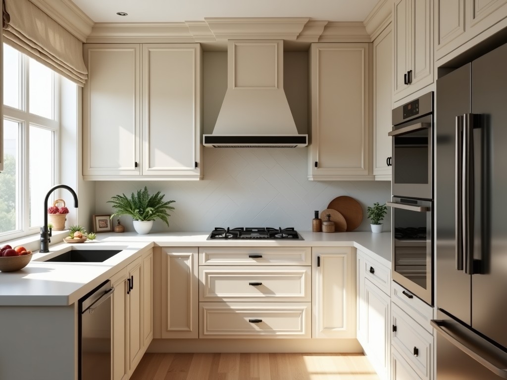
Floor To Ceiling Kitchen Cabinets
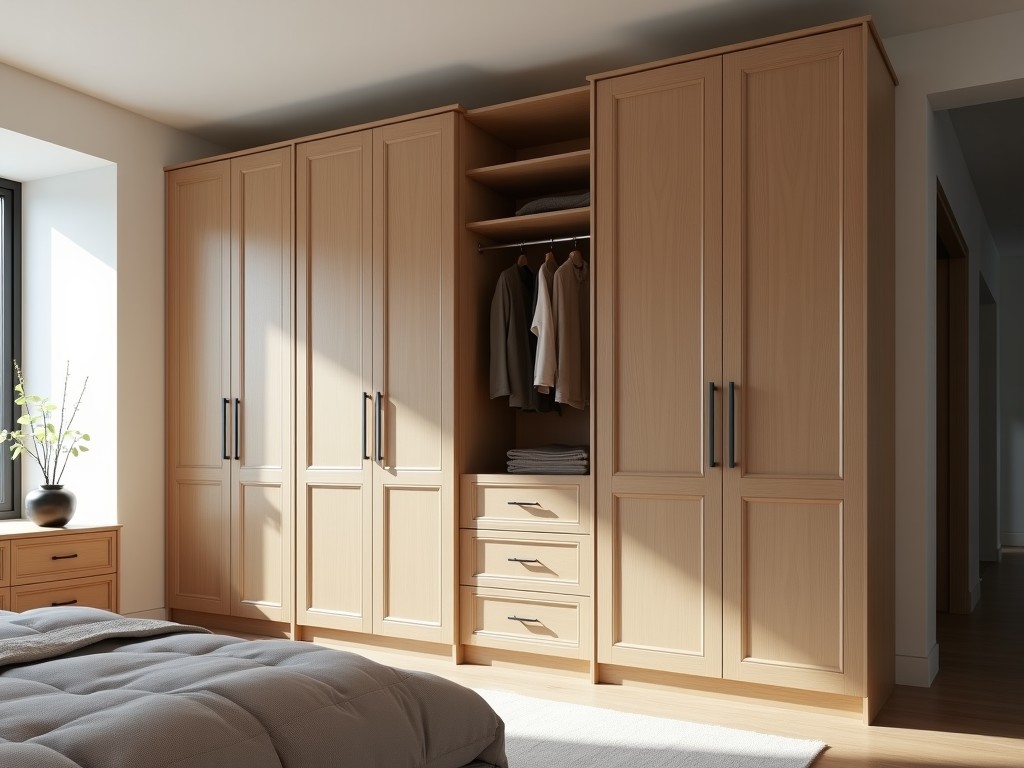
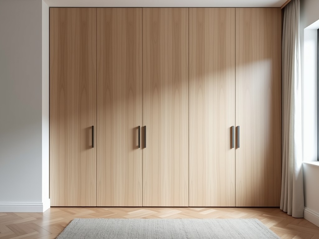
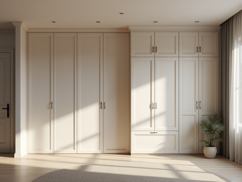
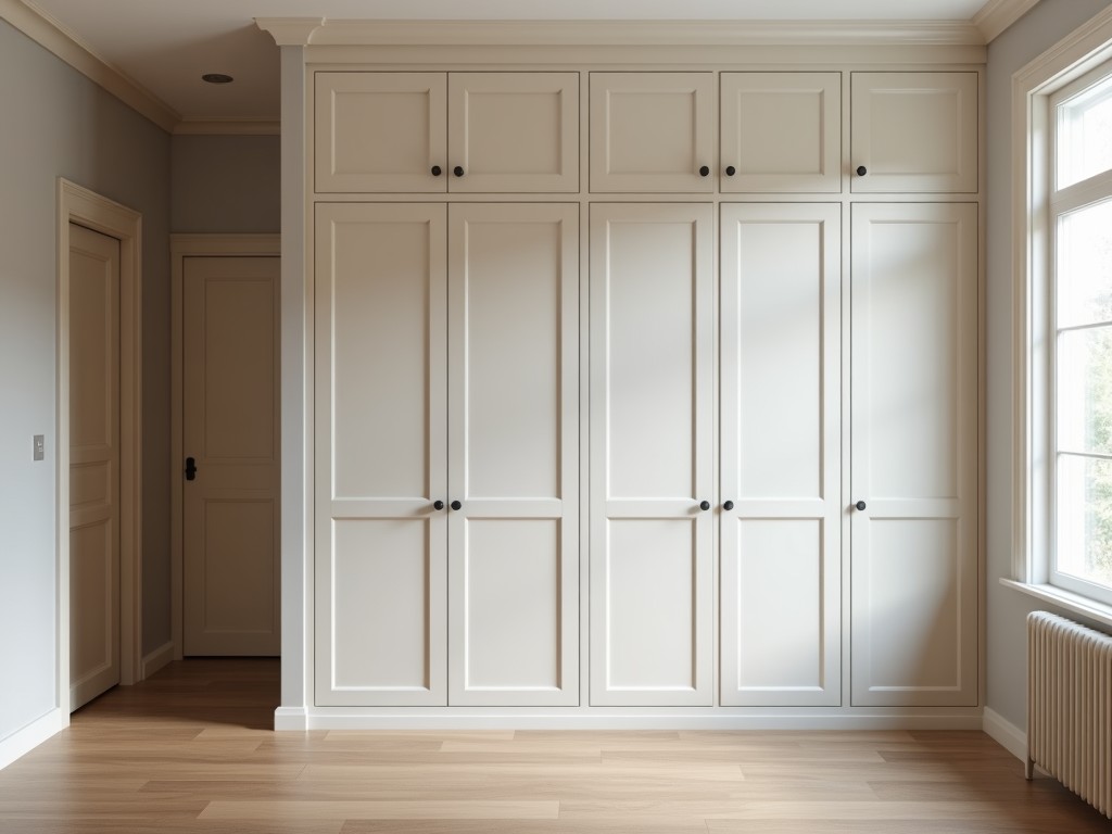
Floor to ceiling kitchen cabinets transfer vertical loads directly to the floor slab through continuous stile and rail assemblies, eliminating reliance on upper wall framing for primary support. This
- Category:
- Kitchen Cabinet
Floor to Ceiling Kitchen Cabinets
Structural Design and Load Distribution
Floor to ceiling kitchen cabinets transfer vertical loads directly to the floor slab through continuous stile and rail assemblies, eliminating reliance on upper wall framing for primary support. This configuration reduces point loading on intermediate wall studs by distributing weight across the full height, typically accommodating 150-200 kg per linear meter when constructed with 18mm plywood carcasses and reinforced with steel brackets at 600mm intervals. The continuous vertical members act as deep beams, resisting racking forces from door operation and appliance vibration through moment resistance in the stile-to-rail joints.
Deflection limits are maintained under L/200 criteria for stile members under combined dead and live loads, calculated using Euler-Bernoulli beam theory with effective length factors accounting for top and bottom rail fixity. Horizontal partitioning at counter height creates a coupled system where upper and lower sections share load through shear transfer via the countertop substrate, reducing bending moments in upper stile members by approximately 40% compared to unsupported tall cabinets. This load path optimization allows for taller configurations without increasing stile cross-section, preserving interior clear opening dimensions.
Material Selection and Dimensional Stability
Cabinet carcasses utilize multi-ply hardwood veneer core panels with cross-banded layers to minimize hygroscopic expansion, typically exhibiting 0.02-0.03% dimensional change per 1% RH shift in controlled environments (40-60% RH). Face frames and doors employ solid hardwood stiles and rails with floating panel construction to accommodate seasonal movement, maintaining joint integrity through tongue-and-groove or splined connections that allow 0.5-0.8mm of seasonal expansion without stress buildup.
Shelf materials specify 3-ply construction with balanced face veneers to prevent warp, supplemented by rear-mounted steel stiffeners for spans exceeding 600mm to limit sag to less than 1.5mm under 25kg uniform load. Edge banding uses 2mm PVC or solid wood with hot-melt adhesive application achieving peel resistance >8N/mm, preventing delamination at humidity cycling conditions per ANSI/KCMA A161.1-2017 standards. These material systems ensure long-term alignment of door reveals and shelf levels critical for floor to ceiling installations where minor deviations become visually amplified over full height.
Installation Tolerances and Field Adjustment
Floor to ceiling installations require precise vertical alignment within ±1.5mm over 2.4m height to prevent cumulative misalignment at door interfaces, achieved through adjustable base leveling systems with 25mm travel and shim-able wall rails featuring slotted holes for horizontal correction. The installation sequence begins with establishing a level datum at the highest floor point, followed by plumb transfer via laser reference to the ceiling track, ensuring carcass verticality accumulates less than 3mm error from floor to ceiling.
Wall attachment uses staggered fasteners at 300mm vertical intervals through the carcass back panel into studs, with each fastener rated for 450kg shear capacity in SPF lumber, providing cumulative withdrawal resistance exceeding 18kN per cabinet unit. Concealed hinge systems incorporate 3-way adjustment (depth, side, height) with 4mm vertical range per hinge, allowing final door alignment compensation for residual wall irregularities without visible gaps or binding at top or bottom doors.
Hardware Specifications and Cycle Life
Full extension concealed drawer slides specify dynamic load capacity of 40kg per pair at 50,000 cycles per EN 15338:2007 Level 2, utilizing roller bearings with reinforced polymer cages and stainless steel races to resist corrosion in high-moisture zones. Soft-close mechanisms employ viscous damping with temperature-stable silicone fluid maintaining closing velocity between 0.15-0.25m/s across -10°C to 40°C ambient ranges, verified through 100,000 cycle endurance testing without performance degradation.
Door hinges for tall applications use 4-bar linkage designs with 110° opening angle and integrated soft-close, rated for 80,000 cycles at 20kg door weight, featuring wear-resistant nylon bushings and hardened steel pins. Adjustable shelving systems specify 5mm diameter steel pins with 15kg point load capacity per pin, inserted into 5mm diameter blind holes spaced at 32mm increments, allowing vertical repositioning while maintaining 95% of original shelf rigidity compared to fixed installations.
Finish Systems and Surface Performance
Catalyzed polyurethane topcoats provide 60-80µm dry film thickness with pencil hardness ≥2H per ASTM D3363, offering resistance to common kitchen contaminants including 10% citric acid, 25% sodium chloride solution, and 70% isopropyl alcohol for 24-hour exposure without gloss reduction >10%. UV-cured finishes achieve full cure in <2 seconds at 300mJ/cm², enabling immediate handling and reducing off-gassing VOCs to <50g/L post-cure, meeting CARB Section 93120 requirements for low-emission coatings.
Edge sealing employs hot-applied polyurea bead with 0.5mm minimum thickness at panel edges, creating a moisture vapor transmission rate (MVTR) <0.5g/m²/24hr at 38°C/90% RH, preventing substrate swelling in humid environments. Surface texture options include matte (10-20 gloss units), semi-gloss (35-45 gloss units), and textured finishes mimicking wood grain through controlled rheology in the coating formulation, all maintaining ΔE<2 color stability under 200hr UV exposure per ASTM G154 Cycle 6.
| Parameter | Typical Range | Test Standard |
|---|---|---|
| Carrying Capacity (Linear Meter) | 150-200 kg | ANSI/KCMA A161.1-2017 |
| Shelf Sag (600mm Span) | <1.5mm | ASTM D3045 |
| Door Alignment Tolerance | ±1.5mm | Factory Audit Standard |
| Finish Hardness | ≥2H Pencil | ASTM D3363 |
| Edge Seal MVTR | <0.5g/m²/24hr | ASTM E96 |
Applications in Commercial and Industrial Kitchen Design
Floor to ceiling cabinets optimize vertical space in facilities with high labor costs where minimizing operator reach distance improves workflow efficiency, particularly in institutional kitchens serving 200+ meals per shift where reduced bending and stretching lowers cumulative ergonomic strain. The continuous vertical storage enables zoning of inventory by frequency of use—daily items at counter height, weekly supplies at eye level, and bulk reserves in upper zones—reducing retrieval time by approximately 18-22% compared to standard height configurations based on time-motion studies in food service environments.
In cleanroom-adjacent food preparation areas, the reduced number of horizontal ledges minimizes particulate accumulation zones, supporting compliance with ISO 14644-1 Class 8 requirements when combined with smooth, non-porous finishes and sealed joints. Pharmaceutical manufacturing support kitchens benefit from the seamless integration with wall panels and ceiling grids, eliminating gaps that could harbor contaminants and facilitating CIP (clean-in-place) procedures for adjacent equipment.
Customization Logic and Engineering Considerations
Height increments are typically aligned with standard stud spacing (406mm or 610mm) to allow direct transfer of loads to structural framing without requiring intermediate blocking, though custom heights can be accommodated with additional steel reinforcement at the top and bottom rails when spanning non-standard floor-to-ceiling dimensions. Interior accessories such as pull-out trays, vertical dividers, and appliance garages are engineered with load paths that transfer forces to the cabinet stile system rather than relying solely on panel strength, ensuring long-term functionality under repeated use.
Ventilation requirements for built-in appliances are addressed through calculated airflow paths that maintain manufacturer-specified intake and exhaust clearances, often incorporating perforated metal panels or ducted plenums integrated into the cabinet structure to avoid compromising structural integrity. Electrical conduit runs are routed through pre-drilled chases in the stile members or via surface-mounted raceways that maintain finish continuity, preventing damage to wiring during cabinet adjustment or reinstallation.
Quality Control and Validation Protocols
Dimensional verification occurs at three critical stages: post-cut panel inspection using coordinate measuring machines (±0.1mm accuracy), sub-assembly check for square and twist (<1.5mm diagonal variance), and final assembly validation of door reveals and shelf levels across the full height. Load testing applies 125% of rated capacity for 24 hours to permanent set criteria, with acceptable deflection recovery >90% after load removal, verified through dial indicator measurements at critical points.
Finish adhesion is assessed via cross-hatch tape test (ASTM D3359 Method B) requiring 5B rating (no peeling or lifting), while impact resistance uses falling ball test (ASTM D2794) with 500g mass from 1m height showing no cracking or delamination. Cycle testing of hardware involves 10,000 operations for drawers and 15,000 for doors under load, monitoring for binding, noise increase >3dB, or loss of soft-close function, establishing baseline performance for field expectations.
Ordering Information and Project Coordination
Quotation requires submission of floor-to-ceiling height measurements at multiple points per wall run, structural wall section details indicating stud size and spacing, and appliance cutout schedules with manufacturer specifications for ventilation and clearance. Lead times typically range from 6-8 weeks for standard configurations after approval of shop drawings, which include detailed section views, hardware schedules, and finish samples for client review.
Packaging specifies individual cabinet units wrapped in polyethylene film with corner protectors, stacked on pallets with interlayer corrugated cardboard and secured with PET strapping, designed to withstand 10-axis vibration testing per ISTA 3E standards. Field support includes detailed installation sequences with shim placement diagrams, adjustment procedures for concealed hardware, and touch-up kits matching the specified finish system for on-site correction of minor transport-related imperfections.